Quantcast
Channel: digital modes – Daniel Estévez
Viewing all 64 articles
Browse latest View live

Listening to the FreeDV net by WebSDR

$
0
0

Since I'm away from my usual QTH, I decided to join yesterday's FreeDV net by listening through the University of Twente WebSDR and giving signal reports on the QSO Finder to the stations transmitting.

I was running Linux, as usual, and FreeDV 1.0.1. To pipe the audio from the WebSDR into FreeDV, I used Pulseaudio, which is my usual solution to send audio between programs. Using pavucontrol, I set the web browser to output to a null sink and then I set FreeDV to record from the monitor of that null sink. In FreeDV, the receive input is set to my pulse ALSA device and the output directly to my soundcard's ALSA device. To avoid clashes between sound devices, I left the transmit devices of FreeDV set to "none".

I also recorded the baseband RF of the whole session by setting Audacity to record from the same null sink monitor. I have prepared an audio file with just the interesting bits.

Signals where quite good on 80m from several stations in Germany and The Netherlands: Frank DL2GRF, Attila DC0ED, and Hans PA0HWB. Hans was having a QSO with Alex OZ9AEC, but Alex's signal was weak and I could only see the pilot tone and traces of the subcarriers on the waterfall. Hans was very strong, between 20dB and 10dB SNR, and his audio was very good. In 40m, I only could copy PA0HWB, and the SNR was going between 5dB and 0dB, giving partial copy, because there was quite a bit of QSB on his signal. Also, there were at least two other stations with signals visible on the waterfall. Eventually, propagation to Italy improved on 40m and I could briefly copy Cristiano IW5EL, both in 1600 and 700B. He was using about 20W to an L-network tuned wire antenna and a homebrew SDR. Very good job indeed.

After the session, I ran my baseband RF recording through FreeDV and recorded the audio of the best parts with Audacity. These are all below and can be listened in the browser or downloaded.

DL2GRF and DC0ED 80m 700B DL2GRF and DC0ED 80m 1600DL2GRF and DC0ED 80m 700B (again)PA0HWB (in QSO with OZ9AEC) 80m 1600The best of PA0HWB 40m 1600IW5EL 40m 1600IW5EL 40m 700B


Decoding LilacSat-2 telemetry

$
0
0

After having my first QSO through the Harbin Institute of Technology amateur radio satellite LilacSat-2, I decided to give a serious try to the telemetry decoding software. This is available as a GNURadio module. A Linux distribution with all the proper software installed and configured is provided, for an easy use. However, I have used GNURadio in the past, so I wanted to try to setup the GNURadio module directly on my machine.

The web page for LilacSat-2 gives also a description of the different telemetry formats. The satellite has an SDR radio transmitting on 437.200MHz. This radio is used for the FM amateur radio transponder and also to transmit several different telemetry formats. The satellite also transmits telemetry on 437.225MHz, presumably using a different (non-SDR) radio and a different antenna, so that the satellite can keep transmitting telemetry even if the SDR system fails. Typically, when the FM transponder is disabled, the satellite will transmit 9k6 BPSK telemetry on 437.200MHz and 4k8 GFSK telemetry on 437.225MHz. These can be seen in the picture above, which was made using my RF recording and baudline. The packet on the upper right is 4k8 GFSK and the packet on the lower left is 9k6 BPSK. Notice the slight slant due to Doppler.

I'm running GNURadio 3.7.7 on my Gentoo Linux machine. I started by cloning the git repository for gr-lilacsat and compiling and installing the GNURadio module. Several GNURadio Companion flowgraphs are provided in the examples folder. There are three different frontends for receiving the telemetry with a FUNcube Dongle Pro+, an RTLSDR or a USRP. It is very easy to create new frontends for anything that can work in GNURadio. There are four telemetry decoders, for different telemetry formats. These will listen in a UDP port and the frontend will send the samples through UDP to the four decoders, which can run simultaneously. The frontend will also record the IQ samples to a file.

There is also another piece of software that will receive the telemetry PDUs from the decoders and upload them to the servers of the Harbin Institute of Technology. This is supposed to be run when decoding and uploading telemetry in real time. As I was going to receive the telemetry without an internet connection available, I didn't mess with this. Therefore, I disabled the block that sends the PDUs by TCP on each of the decoders, because otherwise the decoders will not run if they cannot connect to the uploader program.

I was going to use my FUNcube Dongle Pro+. The frontend for this device uses the module gr-fcdproplus by DL1KSV. I didn't manage to make this module work. I always got some kind of error when importing fcdproplus into python2.7. However, I really don't need to use this module, because I can fetch samples from the Dongle just by using an Audio Source block in GNURadio and set the frequency using Qthid (the decoder expects a centre frequency of 437.260MHz). Therefore, I created a new frontend flowgraph to get samples from an Audio Source block.

The decoder blocks use a custom block called Plan13 CC which performs Doppler correction. You will have to input the TLEs and your coordinates into this block, and it will compute the Doppler shift (presumably according to your computers clock) and correct for it. If you're using the launcher that comes with the software, it should download the TLEs and set your coordinates in all the decoders for you. However, as I'm running the flowgraphs manually, I had to set these data by hand into the block. I also needed to disable the block that imports grc_param.

With all the software set up and seemingly working, I went out to the field (locator IO94ex) with my FUNcube Dongle Pro+ and hand pointed Arrow satellite antenna to decode the telemetry in real time on the 16:46UTC pass of 11/11/2015. Since the satellite transmits using circular polarization, I made no effort to match the polarization and kept roughly a "horizontal" polarization all the time.

Surprisingly, the Doppler correction didn't work at all. It kept using absurd values for Doppler shift during the pass. In the debug information, it also shows the elevation and azimuth to the satellite, and these were wrong as well, so apparently the block has no idea where the satellite is. It might be that it didn't like my TLEs, but I had just copied them from Celestrak and I'm pretty confident I got this right. With the Doppler correction block working badly, I only got one telemetry packet to decode.

Fortunately, I had the IQ recording of the pass. I didn't like this Doppler correction method at all, because it can't be used to process recordings, and this is something that I would be doing to try out several things. Therefore, I used an alternative solution: gr-gpredict-doppler. This GNURadio block allows the Doppler control in Gpredict to update a variable inside the GNURadio flowgraph. This variable can be then used to correct for Doppler by mixing the RF with a cosine signal of the appropriate frequency. The good thing about this is that you can both run it in realtime and use it to process recordings by feeding Gpredict the correct TLEs and using the time control feature.

Another good thing is that it seems that the cosine signal gets updated in a phase continuous manner. When correcting for Doppler, if the correction is not done properly, every time the frequency changes in the middle of a packet, the decoding will fail, because the frequency change messes up the decoder. For that reason, I first ran Gpredict using a 5 second update interval, to minimize the chance of getting an update in the middle of a packet. However, I have also tried using a 100ms update interval and this doesn't seem to upset the decoder at all.

With this setup I managed to decode plenty of packets. I have posted to Gist the PDUs decoded from 4k8 GFSK telemetry and 9k6 BPSK telemetry (obviously the time marks on these logs are not realtime, but taken from the time when I decoded the recording). Surprisingly, I got good decodes even down to about 4º elevation on the LOS. It would be nice to have the binary format for this PDUs, so that I can decode the data, but so far I've been unable to find it.

There are some things that I find a bit weird in the gr-lilacsat flowgraphs. One is that tThe decoder will first shift the 437.200MHz and 437.225MHz signals to baseband and then decimate them to 48kHz. However, no low-pass filtering is applied before decimating, thus aliasing noise and potentially other signals into the desired signal. Another is that, for some reason, although the 9k6 BPSK decoder listens on UDP port 7200, the 1k2 AFKS and FM subaudio decoders listen both on port 7201. Not surprisingly, they don't seem able to listen simultaneously on the same port. The first decoder run will be the one that gets the data. Also, the frontend sends the 437.225MHz samples to ports 7225 and 7226, but no decoder listens on 7226.

Testing microphone performance for Codec 2

$
0
0

Codec 2 is the open source and patent-free voice codec used in FreeDV, a digital voice mode used in amateur radio. Since Codec 2 is designed to be used at very low bitrates (the current version of FreeDV uses 1300bps and 700bps), it does an adequate job at encoding voice, but can't encode well other types of sounds, and thus fails poorly in the presence of noise. Hence, microphones which may be good enough for other applications can give poor results when used for FreeDV (if, for instance, they pick up too much ambient noise or have too much echo). This is a small note about how to test the microphone performance for Codec 2.

I find that a good test is just to make a "loopback" test, where you record your voice with the microphone, encode the voice with Codec 2, decode the encoded digital voice, and listen to the result with headphones to avoid feedback. Doing this in real-time allows one to tune different parameters, such as microphone gain and placement. This loopback can be done easily with the tools c2enc and c2dec from the Codec 2 package and rec and play from SoX.

An easy way to obtain the tools c2enc and c2dec is to compile Codec 2 from source. The source archive can be found in the FreeDV homepage (as of writing this post, the archive for the current version is codec2-0.5.tar.xz). To compile the code, run

mkdir build
cd build
cmake ..
make

in the source folder. Then c2enc and c2dec may be found under src/ in the build folder.

The loopback test can be run as

rec -t raw -r 8000 -e signed-integer -b 16 -c 1 - | \
./c2enc 1300 - - | ./c2dec 1300 - - | \
play -t raw -r 8000 -e signed-integer -b 16 -c 1 -

(from build/src). As I'm using PulseAudio, I can select the input and output devices on the fly using pavucontrol.

This loopback test runs Codec 2 at 1300bps. A nice thing is that there is some delay in the loop, which I find better to hear myself back properly. Variations of this loopback test are also interesting. One can replace 1300 by 700B to run Codec 2 at the 700bps mode used in FreeDV 700B. One can also remove c2enc and c2dec from the pipeline to listen to the analog audio. Note that the sampling rate is 8kHz, which is adequate for communications quality, but is far from being Hi-Fi. The parameter -r 8000 can be replaced with -r 44100 or -r 48000 for Hi-Fi quality (but not when running the Codec 2 tools, which expect a 8kHz sampling rate and won't really benefit from a higher sampling rate).

Decoding packets from GOMX-3: modulation and coding

$
0
0

Recently, Mike DK3WN pointed me to some decoder software for the satellite GOMX-3. This satellite is a 3U cubesat from GomSpace and transmits in the 70cm Amateur band. It has an ADS-B receiver on board, as well as an L-band SDR. As far as I know, no Amateur has decoded packets from this satellite previously, and Mike had some problems running the decoder software. I have taken a look at the software and tried my best to decode some packets from GOMX-3. So far, I have been able to do Reed-Solomon decoding and get CSP packets. However, I don't have the precise details for the beacon format yet. Here, I describe all of my findings.

In my system, the GNUradio decoder from GomSpace builds and runs without problems. The only special thing I see about this OOT-module is that it uses ZeroMQ. I don't know if GNUradio comes with ZeroMQ support built by default. In Gentoo, this is just a USE option. Presumably, the dependency on ZeroMQ could easily be removed from the decoder, because it is only used to pass the packets to some telemetry decoding software that I've been unable to find.

The data I've been using for my experiments is an IQ recording that I made during this month's V-UHF contest. The antenna I used was just a 50cm whip on top of my car. Despite this, some packets are up to 14dB over the noise floor and I get several decodes with 0 byte errors.

The modulation used by GOMX-3 is GFSK at 19200 baud. It seems that it has used lower baudrates in the past, but now it is running at 19k2. The satellite transmits CSP packets. These are Reed-Solomon encoded. The Reed-Solomon code used is the recommended by the CCSDS in their TM Synchronization and Channel Coding book. In fact, GomSpace's decoder uses the implementation by Phil KA9Q of CCSDS Reed-Solomon.

On top of the Reed-Solomon coding, a scrambler is used. After reading the code a bit, it turns out that this scrambler is the very same one that is used in G3RUH 9k6 AX.25 packet radio (this is the standard for Amateur packet radio at 9600 baud). This is just a multiplicative scrambler with polynomial 1 + x^{12} + x^{17}. Although the decoder from GomSpace has its own descrambler block, one can also use GNUradio's Descrambler block with Mask=0x21 and Length=16 (more on this in a future post).

The interesting thing about GOMX-3 scrambling is that the preamble is not scrambled, in contrast to G3RUH 9k6 packet radio. In AX.25 packet radio, the preamble is a sequence of HDLC flag bytes (the bits 01111110). In G3RUH 9k6 these bytes are scrambled, so at first sight they just look random. However, GOMX-3 transmits a sequence of the bits 01 which is not scrambled. After that, the scrambled syncword begins. You can see this perfectly in the picture below, which shows the baseband (FM demodulated) data. It is also possible to see this effect in the waterfall picture on top of this post. Since the preamble is periodic, it essentially generates just 3 frequencies when it is FM modulated. Thus, the preamble looks different from the scrambled data, which appears as a block of white noise. In contrast, G3RUH 9k6 packets just look like a block of noise. Not scrambling the preamble is probably a good idea, as it may help to do clock recovery, because the start of the packet is a very simple signal.

Baseband data from GOMX-3 (dB scale)

It is important to note that, even though the transmission changes from unscrambled to scrambled at the start of the syncword, no special measures should be taken while descrambling. Applying the descrambler to the whole stream of bits will transform the preamble into garbage, but it will descramble correctly the syncword and data. This is because the switch from unscrambled transmission to scrambled transmission is entirely handled by the transmitter (this can be accomplished, for instance, by loading the correct seed in the LFSR when scrambling starts).

Another difference between G3RUH 9k6 packets and GOMX-3 packets is that G3RUH uses NRZI coding, while GOMX-3 uses plain NRZ coding (a 1 is transmitted as a positive frequency shift and a 0 is transmitted as a negative frequency shift). Thus, it is important to preserve the polarity of the baseband FM-demodulated signal. For some reason, Linrad inverts the polarity, so I have to compensate for this by inverting the signal again in GNUradio.

The syncword used is 0x930B51DE (in big-endian format). Keep in mind that it is sent scrambled, so it is impossible to see it just by looking at the figure above. The next byte after the syncword contains the length of the Reed-Solomon coded data plus 1 (to include this byte in the length count), as an 8-bit unsigned integer. The Reed-Solomon coded data comes after this length byte. I think this length byte is potentially a bad idea, since a bit error in this byte will most likely make the packet much harder to decode.

The data encoded with Reed-Solomon is organized as follows. The first byte is the total length of this data (also counting this byte). The next 4 bytes are the CSP header. For some strange reason, the CSP header is in big-endian format (it should be little-endian). The decoder from GomSpace takes care of this by swapping the bytes around. The remaining bytes are the palyoad of the CSP packet.

The code I'm using can be found in my fork of gr-ax100. In the next post, I'll talk about the contents of the CSP packets. For now, I'm just leaving you a very small packet from GOMX-3. Next time, I'll tell you what this packet is.

------------ FRAME INFO -------------
Length: 29
Bytes corrected: 0
Dest: 10

* MESSAGE DEBUG PRINT PDU VERBOSE *
()
pdu_length = 28
contents = 
0000: 01 01 af 8a 00 01 02 03 04 05 06 07 08 09 0a 0b 
0010: 0c 0d 0e 0f 10 11 12 13 cc 79 eb e6 
***********************************

KISS, HDLC, AX.25 and friends

$
0
0

A while ago, I uploaded my gr-kiss out-of-tree GNUradio module to Github. This is a set of blocks to handle KISS, HDLC and AX.25, which are the protocols used in amateur packet radio. There are several other OOT modules that do similar things, but I didn't like the functionality of them very much. While programming this module, I've also noted that the documentation for these protocols is not so good sometimes. Here I'll give a brief description of the protocols and explain how everything works together.

KISS The KISS protocol was originally designed to interface a computer with a TNC (Terminal Network Controller). Think of the TNC as a sort of modem that does some modulation and low level framing functions. The idea of KISS is to move most of the processing to the host computer. Before KISS, a TNC usually performed some AX.25 related tasks. However, a KISS TNC only works with HDLC and passes raw AX.25 frames to the host. The KISS protocol is described here. It provides a way to separate frames and to send commands to the TNC. Since this protocol is so simple, it is also used in many situations where no TNC is involved. In this case, it is just used to divide a stream of data into frames. Thus, a series of packets can be saved to a file "in KISS format". These packets are usually AX.25 frames, but this need not be the case. Also, different pieces of software can exchange packets using the KISS format.

The end of a frame is marked by the byte 0xC0. The start of a frame need not be explicitly marked (but it is usually also marked with 0xC0). Several consecutive 0xC0 bytes may appear. This doesn't mean that there are empty frames between them. Empty frames are not allowed. The first byte of any frame is used to send commands to the TNC. When a TNC is not involved, the first byte is 0x00. Then the real frame bytes come after it. The byte 0xC0 can not appear anywhere inside a frame. If the data contains this byte, it is replaced by 0xDB 0xDC. If 0xDB appears in the data, it is replaced by 0xDB 0xDD.

HDLC The HDLC protocol is a data link layer protocol used in X.25 and other protocols. In AX.25, only a few functions of HDLC are used to do framing and frame integrity checking. The first remark is that usually HDLC is NRZ-I encoded. This means that a logical 0 bit is marked by a change of state (say, by changing from a positive frequency deviation to a negative frequency deviation or vice versa), and a logical 1 bit is marked by no change of state. The end of frame marker is the sequence 01111110 (or 0x7e). Note that other NRZ-I implementations follow the opposite convention. This is also used to mark the start of a frame and between frames as an idle signal. Before a frame is transmitted, several 0x7e bytes are sent to help the receiver synchronize. Also, after the frame is transmitted, it is usual to send the byte 0x7e several times to ensure that one of these flags is received without errors.

HDLC avoids long runs of 1's (which will make the receiver loose synchronization) by forbidding more than 5 consecutive 1's in the data (except for the 0x7e marker, where 6 consecutive 1's appear). Every time that 5 consecutive 1's appear in the data, a 0 is inserted after them. This is known as bit-stuffing. Of course, when the receiver gets 5 consecutive 1's, if the following bit is a 0 it should be ignored, and if it is a 1, the receiver should expect that the following bit is a 0, as this must be the last bit of the 0x7e marker.

Another important aspect of HDLC is that each byte is transmitted starting with the least significant bit. This is the opposite way as in many other protocols. The last function of HDLC that is used in AX.25 is the frame check sequence (or FCS). This is a 16 bit checksum that is appended to the data frame. The checksum is computed using CRC-16-CCITT. The FCS is sent least-significant-byte first (and remember that each byte is sent least-significant-bit first and that bit-stuffing is done).

Keep in mind that since HDLC uses NRZ-I, it isn't sensitive to the polarity of the signal. Thus a signal can be inverted in polarity without causing problems. For this reason, when BPSK is used to transmit HDLC frames, differential encoding is not used.

AX.25 The AX.25 protocol is a data link layer used by amateur radio. The framing and FCS is done using HDLC as described above. The AX.25 frames do not include the FCS or any other checksum. The details of the protocol are here. When reading that document, keep in mind that the 0x7e flags and the FCS are not really part of the AX.25 frame. This protocol has many features and it won't be described here. Since Linux can handle AX.25, it is useful to know how Linux can be used to deal with AX.25. Also, Wireshark can be used to inspect and analyse AX.25 frames.

Modulations It is also important to know how AX.25 HDLC frames are actually transmitted over the air. The first way to do it is using AFSK. This is normally used for a rate of 300 baud on the HF bands. The NRZ-I bits are transmitted as an audio signal which frequency shifts between two tones spaced 200Hz apart. The radio is set to SSB mode, so the actual emission is really FSK. The particular tones that are used are not standard, so this has to be compensated by setting the radio dial frequency correctly. It is not important whether LSB or USB mode is used, because the signal is not sensitive to polarity inversion.

The second way to do it is using FM AFSK. This is normally used for a rate of 1200 baud on the VHF and UHF bands. The NZR-I bits are transmitted as an audio signal which frequency shifts between the tones 1200Hz and 2200Hz. This audio signal is FM modulated before transmission.

The third way to do it is using G3RUH FSK. This is normally used for a rate of 9600 baud on the UHF bands. The HDLC bitstream is scrambled using a multiplicative scrambler with polynomial 1 + x^{12} + x^{17} before NRZ-I encoding is done. The NRZ-I signal is then shaped (low-pass filtered) and used to drive an FM modulator directly, in order to produce an FSK signal.

The fourth way to do it is using BPSK. This is used in a few amateur satellites, using a rate of 1000 or 1200 baud. The NRZ-I bits are transmitted as a BPSK signal (differential encoding is not used). This BPSK signal can be generated as an audio signal on a computer and then used to drive an SSB transmitter.

Finally, fldigi can act as a KISS TNC, allowing to send AX.25 frames in many of the modes supported by this program. However, these digital modes are normally used for text based chat and rarely used for AX.25.

gr-kiss includes example flowgraphs showing how the 1k2 FM AFSK, 9k6 FSK and 1k2 BPSK modulations work.

Interfacing AX.25 with Linux As we have stated above, it is sometimes useful to interface an AX.25 system with Linux. To use the AX.25 functionality of Linux, first one needs to declare a "port" for each AX.25 interface that Linux will handle. The ports are declared in /etc/ax25/axports.

# /etc/ax25/axports
#
# The format of this file is:
#
# name callsign speed paclen window description
#
test	EA4GPZ-10	38400	2000	2	test
test2   EA4GPZ-9	38400	2000	2	test2

This is an example. The speed is not very important if these ports won't connect to a hardware TNC through a serial (RS232) port.

Each of the ports needs to be attached to a serial port or a pty device (a sort of virtual serial port). If we want to connect some AX.25 software to a Linux AX.25 interface, we can use two tools: kissnetd and socat. kissnetd is used to create a pair of pty devices which are connected together. Everything written to one of the pty devices can be read on the other one and vice versa. This is fine if our AX.25 software can read and write to a pty device.

As an example, let's use kissnetd to send a KISS file to a Linux AX.25 interface. This can be used to analyse the frames with wireshark, by making wireshark capture traffic on the AX.25 interface.

# kissnetd -p 2 &
kissnetd V 1.5 by Frederic RIBLE F1OAT - ATEPRA FPAC/Linux Project

Awaiting client connects on:
/dev/pts/6 /dev/pts/7

# kissattach /dev/pts/6 test
AX.25 port test bound to device ax0
# cat file.kiss > /dev/pts/7

socat is a much more flexible tool. It is also used to make two "devices" which are connected together. However, it supports a number of different devices: pty's, TCP and UDP sockets, files, pipes, UNIX sockets... As an example, let's use socat to connect a pty with an UDP socket and then send a KISS file by UDP.

# socat PTY,link=/tmp/serial UDP-LISTEN:1234 &
# kissattach /tmp/serial test
AX.25 port test bound to device ax0
$ nc -4u localhost 1234 < sats/firebird-4-2015032418.kiss 
nc: using datagram socket

As another example, we can use socat to set up a TCP client that connects to one of the examples in gr-kiss.

# # run the example in gr-kiss
# socat PTY,link=/tmp/serial TCP:52001 &
# kissattach /tmp/serial test
AX.25 port test bound to device ax0

Basic usage of Linux AX.25 interfaces Linux AX.25 interfaces can be configured for IPv4 in the same way as any other network interface. Then, the usual tools for IP traffic can be used. There are several other tools specific to AX.25. listen can be used to monitor AX.25 traffic. Keep in mind that Wireshark can also capture and analyse traffic in AX.25 interfaces. call can be used to make AX.25 connections. It is also an easy way to generate test packets.

Using the CC1101 and Beaglebone black for IP traffic on 70cm

$
0
0

Lately, I have been experimenting with using a CC1101 chip together with a Beaglebone black single board ARM computer to transmit IP traffic over the 70cm Amateur band. There has been a similar project from OEVSV, but I've never seen this project reach a final form. Edouard F4EXB has some code that uses the Raspberry Pi instead. Presumably, this will suffer from problems when using the higher data rates supported by the CC1101, as his software is not real-time.

The goal of my project is to build an affordable 70cm IP transceiver with a power of a few Watts. This can be used in the Hamnet Amateur Radio IP network. The modulation should not use more than a couple of hundreds of kHz's of spectrum, as it doesn't seem very sensible to take up much more spectrum in the 70cm band. Although the usual maximum bandwidth in the 70cm band is 20kHz, the IARU R1 bandplan allows for wideband experiments around 434.000MHz. A data rate of 128kbps with MSK modulation seems about right, as it uses roughly 200kHz of spectrum. Further on-the-air tests will perhaps change these parameters a bit.

The CC1101 is a transceiver chip from Texas Instrument that is able to do up to 600kbps using different digital modulations (FSK, GFSK, 4-FSK and MSK). It supports packet-based transmissions using RX and TX FIFOs and can be programmed through a SPI interface. It is quite inexpensive and popular, and there are several modules in the market that include the CC1101 and an RF amplifier in a small board (the CC1101 by itself goes only up to 10dBm). For instance, the RFC-1100H I'm using includes a 2W PA. One has to be a bit careful with these amplifiers, as they lack filtering after the amplifier and will probably need a low-pass filter to comply with the regulations. Also, they may suffer from thermal issues during long transmissions.

The hamnet-cc1101 code I've programmed uses one of the Beaglebone black PRU's (Programmable Realtime Units). These are two 200MHz 32bit special purpose processors that are embedded in the TI ARM chip that the Beaglebone uses. They are intended for real-time applications and can be programmed using an assembler code that runs at one instruction per clock cycle. Initially, I wanted to make my code a regular user-space program. However, I found out soon that the 64byte buffer of the CC1101 empties quite fast (in 4ms at 128kbps), so the code should run often enough to refill the buffer. The problem is that a Linux user-space program can be forbidden to run for several milliseconds while the kernel is busy serving interrupts. Therefore, I have ended up using the PRU to interface with the CC1101.

The PRU runs some assembler code that controls the CC1101 through SPI by bit-banging some PRU I/O pins. The communication between the PRU code and the user-space Linux code is through the PRU RAM. Each PRU has 8kB of dedicated RAM that can be mmap()ed by a user-space program. The user-space code just writes and reads to some buffers on the PRU RAM. This hides away all the complexity in the PRU code and makes it possibly to implement easily different FEC codes and checksums in the user-space code.

So far, I'm using a CRC-32 checksum and no FEC, but perhaps I'll do some tests with some low-overhead FEC in the future. The packet format I'm using is as follows:

  • 2 bytes. Big-endian 16bit unsigned integer. Length of the whole frame.
  • n bytes. Ethernet frame.
  • 4 bytes. CRC-32 of the whole frame (big-endian).

By maintaining a simple packet format, this system can be interfaced with others, as the CC1101 supports a wide range of digital modulations and rates. However, nothing stops one of using a really complex FEC, beacause the Beaglebone has enough CPU power to handle this at the (relatively) low data rates used.

The user-space code creates a TAP device to allow access to the CC1101. This can be treated as a regular ethernet device, so IPv4, IPv6 and/or BPQ AX.25 can be used over this interface.

While programming this project, I've found that the documentation on the web about how to start programming the PRU in assembler is not so good. The book Exploring BeagleBone has been very useful to understand how the PRU works and get this up and running.

I am testing the stability of my code by running two of these CC1101 modules at home, each on its own Beaglebone black. One of them is connected to my Hamnet network, using a bridge between the TAP interface and the ethernet interface. I use the other one connected to my laptop by USB and bridging the TAP interface and the ethernet over USB interface. This allows me to access Hamnet from my laptop. There are 3 floors in vertical between both devices and I'm using a power of 10dBm (I keep the PA off). So far, it seems to work well. The data rate doesn't allow for video streaming, but mumble and echolink work without problems.

Receiving the Vaisala RS92-SGP radiosonde launched from Madrid-Barajas

$
0
0

Each day, at 01:00UTC and 11:00UTC a Vaisala RS92-SGP radiosonde is launched from Madrid-Barajas airport. This is a small electronics package tied to a helium balloon that ascends up to between 24 and 28km high before bursting and descending on parachute. It is designed to measure atmospheric parameters on its way up. It includes temperature, pressure and humidity sensors, as well as a GPS receiver. The launch on Wednesdays at 11:00UTC also includes a plug-in ozone sensor (which is a much larger and more expensive package). The data is transmitted at 403MHz using Manchester-encoded 4800bps GMSK and protected using Reed-Solomon. You can find more information about the RS92-SGP model in its technical datasheet and about the launches at Madrid-Barajas and other launches in Spain in the Spanish AIP Section 5.3 (other activities of a dangerous nature). Also, there is somebody who feeds the radiosonde data into the APRS network using SM2APRS, so you can track the launches by following OKER-11 on aprs.fi.

Usually, the Sondemonitor software is used to receive and plot the parameters measured by the radiosonde and track the GPS data. Of course, this program is very nice and complete, but it is shareware, costs 25€ and runs only in Windows. I wanted to try if it is possible to track the GPS data in Linux using free software.

There is German receiver software on Github that supports the RS92-SGP model, as well as several others. The software is very crude and comes without any licence statement. However, it works and I guess it is OK to use it (I could contact the author about the licence). There are some German users posting their experiences on some forum, but I find it hard to track down the useful information there, so I've got this up and running by myself.

The program that I will be using is rs92/rs92gps.c. It can be compiled just by doing

gcc -O2 -lm -o rs92gps rs92gps.c

This programs needs the GPS almanac and ephemeris data, because it seems that the radiosonde doesn't send the GPS coordinates but rather the GPS time-of-flight data (or something similar), so all GPS calculations have to be done on the receiver. The current SEM almanac can be downloaded from Celestrak. For the ephemeris, look here:

ftp://cddis.gsfc.nasa.gov/gnss/data/daily/YYYY/DDD/YYn/brdcDDD0.YYn.Z (updated)
ftp://cddis.gsfc.nasa.gov/gnss/data/daily/YYYY/brdc/brdcDDD0.YYn.Z (final)

As you can see on this youtube video (RS92-SGP starts at 00:50), the program just plots line by line the GPS positions reports, using its own human readable format. My idea is to use a small python script to turn this data into NMEA sentences and feed those to gpsd. Then Viking (or any other GPS mapping software) can be used to track the data on a map.

The python script goes as follows:

View the code on Gist.

To run everything we do:

mkfifo /tmp/gps
sudo chmod 666 /tmp/gps
sudo gpsd /tmp/gps
rec -t wav -r 48000 - | stdbuf -i0 -o0 -e0 ./rs92gps -a almanac.sem.week0886.405504.txt -e brdc2290.16n.Z -i | ./gps.py > /tmp/gps

Here, you should substitute the current almanac an ephemeris files and use the parameter -i or not depending on your receiver (this parameter inverts the FSK waveform).

Then, in Viking it is as easy as adding a GPS layer, then right-clicking it and selecting "Start Realtime Tracking" to get the GPS data. The commands gpspipe -r and gpsmon are useful to check if the receiver is working.

Below, you can see the map for today's afternoon launch. You can note that there are lines extending out to bogus positions. The reason for this is that although the data is RS-encoded, the receiver software doesn't do any kind of error checking or correction, so sometimes you'll get incorrect data. However, the incorrect GPS positions are very easy to spot. The reception of the radiosonde has being done in the worst possible conditions: I've being using my fixed 6m and HF antennas, as this was easier to set up for me. The signal received with a 2m/70cm handheld radio just standing out in my garden is much better. Nevertheless, this setup has being enough to test the software, as the signal from the radiosonde is indeed quite strong.

Radiosonde GPS path launch 16/08/2016 11:00UTC

How hard is it to decode 3CAT-2?

$
0
0

In a previous post, I looked at the telemetry packets transmitted by the satellite 3CAT-2. This satellite transmits 9600bps AX.25 BPSK packets in the Amateur 2m band. As far as I know, it is the only satellite that transmits fast BPSK without any form of forward error correction. LilacSat-2 uses a concatenated code with a (7, 1/2) convolutional inner code and a (255, 223) Reed-Solomon outer code. The remaining BPSK satellites transmit at 1200bps, either using AX.25 without FEC (the QB50p satellites, for instance), or with strong FEC (Funcube, for example). Therefore, I remark that 3CAT-2's packets will be a bit difficult to decode without errors. But how difficult? Here I look at how to use the theory to calculate this, without resorting to simulations.

The bit error rate of BPSK in an AWGN channel is known to be

P_b = \frac{1}{2}\operatorname{erfc}\left(\sqrt{\frac{E_b}{N_0}}\right).

Here, P_b is the probability that a bit is decoded erroneously, E_b is the energy per bit (in Joules), N_0 is the noise power spectral density (in W/Hz, which is the same units as Joules), and \operatorname{erfc} denotes the complementary error function, defined by

\operatorname{erfc}(x) = \frac{2}{\sqrt{\pi}}\int_x^\infty e^{-t^2}\,dt,

While E_b/N_0 is a useful parameter to compare different modems, when talking about signal strength it's more practical to use carrier to noise ratio, or C/N. Here C is the power of the signal (in W) and N is the noise power in the bandwidth B to which the signal is filtered (in W again). Therefore, for a bitrate b (in bit/s), the relation between these two parameters is

\frac{C}{N} = \frac{b}{B}\frac{E_b}{N_0}.

For the case of 3CAT-2, b = 9600\mathrm{bit/s} and B is about 15kHz.

Since AX.25 uses no form of error correction (it only uses CRC-16 error checking), all the n bits of the packet have to be received successfully. In an AWGN the bits are independent random variables, so the probability that the packet is received OK is

P_{\mathrm{OK}}=(1-P_b)^n.

For the case of 3CAT-2, the packets are 86 bytes long, including the AX.25 headers. To this, we have to add 2 bytes for the CRC and 2 bytes for each of the 0x7e flags marking the beginning and end of the packet, giving a total of 90 bytes. Thus, n=720\ \mathrm{bits}. In practice, n will be slightly larger than this due to bit-stuffing. We will ignore this difference, as the results are not very sensitive to the value of n.

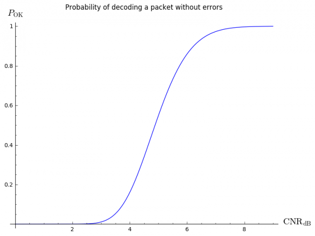
Using all these ingredients, we can plot the following curve.

cnr

You can see that the threshold for successful decoding is around 5 or 6dB CNR. This plot was done in Sage using the following code:

plot(lambda CNRdB:
     (1-0.5*pari(sqrt(15/9.6*10^(CNRdB/10))).erfc())^n,
     (x,0,9),
     axes_labels=["$\mathrm{CNR}_{\mathrm{dB}}$", "$P_{\mathrm{OK}}$"],
     title="Probability of decoding a packet without errors")

However, CNR is not an parameter which is easy measure directly. We are much more used to talk in terms of signal plus noise to noise ratio, or (S+N)/N. This is by how much the signal meter increases when receiving the signal versus when receiving only the noise floor. The relation between the two is straightfoward:

\frac{S+N}{N} = \frac{C}{N} + 1.

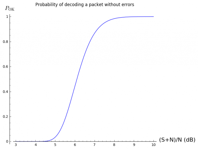
However, when writing this relation in dB's, it becomes a bit complicated and difficult to compute mentally. The rule of thumb is that a 3dB (S+N)/N corresponds to 0dB C/N (obvious), and that for high values (say greater than 10dB), both parameters are more or less the same. We can plot a similar curve in terms of (S+N)/N.

snr

You can see that the threshold for successful decoding is between 6 and 7dB (S+N)/N. This was done with:

plot(lambda SNNRdB:
     (1-0.5*pari(sqrt(15/9.6*(10^(SNNRdB/10) - 1))).erfc())^n,
     (x,3,10),
     axes_labels=["(S+N)/N (dB)", "$P_{\mathrm{OK}}$"],
     title="Probability of decoding a packet without errors")

Although in reality the channel behaves worse than an AWGN channel (typically it can be modelled as a fading channel), the threshold around 6 or 7dB (S+N)/N matches up quite well with what I've seen in the recordings. The packet that I managed to decode from Scott K4KDR's recording was 7dB (S+N)/N. The remaining packets, which I couldn't decode, where 5dB (S+N)/N or weaker. In Jan PE0SAT's recording, there are several packets with (S+N)/N between 10dB and 15db, and I was able to decode 10 of these.

Almost everything that I've done here can be used for 1k2 AX.25 BPSK. Since both b and B scale down by the same factor of 8, the ratio b/B stays the same. The only difference is that N will scale down by a factor of 8, or -9dB. Thus, to achieve a particular value of CNR or (S+N)/N, the 1k2 signal can be 9dB weaker than the 9k6 signal. Of course, this is a huge difference.

However, to put things into perspective, one has to remember that there are plenty of 9k6 or faster AX.25 FSK satellites working, many of which are easy to receive. As this image shows, for a given bit error rate, BPSK is about 2dB better than FSK, so a 9k6 AX.25 BPSK modem can work fairly well for a VHF or UHF satellite.


A brief try at decoding HORYU-4 1k2 AFSK telemetry

$
0
0

In the previous post I've talked about HORYU-4 CW telemetry. Here I report my findings when trying to decode 1200baud AFSK telemetry. Since the satellite transmits digital telemetry only over Japan, the recordings I've analysed have being kindly provided by Tetsurou JA0CAW. There is a telemetry format document from Kyutech, but as it is the case with the CW document, it is rather incomplete and lacks several important details.

The document gives the impression that a custom packet format is used, where the start of the packets is marked by 0xdd 0xdd and the end is marked by 0xaa 0xaa 0xaa. However, HORYU-4 transmits standard AX.25 frames. The packets that are described in the document are embedded as the payload of the AX.25 frame. Therefore, the frames can be decoded with any software TNC for 1k2 packet radio. In theory, it should be possible to ignore the AX.25 wrapper up to some extent and use the embedded packet only, correcting for errors using the Hamming codes that are included in the packet. This would be advantageous, because AX.25 uses a CRC-16 checksum, which isn't able to correct errors. However, to do this one should first understand how these Hamming codes are supposed to work, and I haven't managed to do it yet.

I've used Direwolf as an AX.25 decoder, as it is better (and more complex) than a simple decoder implemented in GNUradio. The list of packets decoded is in this gist.

As you can see, some of the packets only contain garbage, mostly in the form of 0x22 or 0xaa bytes. The rest seem to follow the format that is described in the document: 85 bytes which start by 0xdd 0xdd and end by 0xaa 0xaa 0xaa (note that there are always two extra 0x00 bytes at the end of the packet).

The first obvious remark is that there is very little data in the packets. The header (first 7 bytes including the leading 0xaa's) contains information, but the mission log (the remaining bytes) contains few non-zero entries.

The document says that every third byte in the packet is a Hamming code, presumably for the two bytes before it. However, none of the usual Hamming codes produces 8 or less check bits out of 16 message bits, so it must be some unusual implementation. I had the idea to "reverse engineer" the Hamming code. If you assume that each Hamming code is a linear function of the two bytes before it, then with enough samples you can find that linear function. However, this doesn't work, due to the following triplets of bytes, where the last byte is presumably the Hamming code for the first two bytes: 0x12 0x31 0x05, 0x12 0x31 0x23, 0x12 0x31 0x49. Clearly the Hamming code for the bytes 0x12 0x31 should be the same all the time. Either I have no clue about how Hamming codes are being used or something is wrong.

Also, the first bytes of the mission log don't agree well with the document. For instance, take 00 00 00 13 00 e1 39 70. The first two bytes are the "total days". A value of 0 makes sense here if the counter resets often. The third byte is the Hamming for the first two bytes, which seems OK. The fourth byte is the "total hours". Here, 0x13 = 19 hours, which makes sense. Moreover, all the bytes that appear in this position in other frames are smaller than 0x17 = 24 hours, which is fine. The next byte is "total minutes". Here we have 0, which can be OK. In other frames we have values not exceeding 0x3c = 60 minutes. Moreover, the other "total time" that appears is 18 hours and 49 minutes, which makes sense given that all the packets are probably from the same pass. The next byte is the Hamming for the two preceding bytes. Its odd behaviour has been mentioned already. The next byte is supposed to be the mode. Here we have 0x39, but this value doesn't appear in the list of modes. In other packets we have the values 0x31, 0x37, 0x3a, which don't appear in the list of modes either. I have the impression that this value is not mode but "seconds". These would make sense given the three packets in the same recording with values 0x31, 0x37, 0x3a. I don't know what to make of the next byte. In this case it's 0x70. In other packets it has the values 0xc0, 0x60, 0x20. This doesn't seem to be the mode either. 0x70 and 0xc0 don't appear in the list of modes and it would be unlikely that the satellite changed modes so fast.

So, altogether it seems that there is little useful information in these packets. It bugs me that, even with the document at hand, I've been able to figure out very little about the format and the Hamming code used in the telemetry.

Some notes on BEESAT and Mobitex-NX

$
0
0

The family of BEESAT satellites from the TU Berlin transmit telemetry on the Amateur bands using the Mobitex-NX protocol. Some of the BEESAT satellites also include a digipeater using this same protocol. There is a GNUradio implementation from TU Berlin of a software TNC for these satellites. This software has some shortcomings (for instance, FEC decoding wasn't working properly). I've made my own fork where I've fixed some of the problems. Here I'll talk about various aspects of the Mobitex-NX protocol and the GNUradio implementation.

The details about how the Mobitex protocol works can be read in the MX909A datasheet. Many thanks to Andy UZ7HO for pointing me to this document. The only difference between the standard Mobitex protocol and the Mobitex-NX protocol is that a callsign is included after the frame header and before the data blocks. The callsign is transmited as 6 bytes in ASCII followed by a 2 byte CRC-16CCITT (this is the same CRC that is used in AX.25). Therefore, the contents of a Mobitex-NX frame are as follows:

  • Bit sync. The pattern 0xcc repeated several times.
  • Frame sync: 0x0ef0
  • Control. 2 bytes (see below for the contents)
  • FEC of control (1 byte, containing 4 parity bits for each control byte)
  • Callsign. 6 bytes in ASCII
  • CRC-16CCITT of Callsign. 2 bytes
  • Several data blocks. Each data block is 30 bytes long

The contents of the control bytes are:

  • 2nd byte, bit 1. ACK bit. If this bit is set, the packet is requesting an ACK.
  • 2nd byte, bit 0. Baud bit. If this bit is set, the packet is transmitted in double baudrate (9600bps) mode. The beginning of the packet is always transmitted at 4800bps. A double baudrate packets uses some more fields to accommodate for the baudrate change. This won't be described in this post.
  • 1st byte, bits 5 through 7. Message type. See below.
  • 1st byte, bits 0 through 4. Number of data blocks minus one. The number of data blocks in the frame is one plus the value of this field, so any number of blocks between 1 and 32 is possible. This field can also mean "number of errors", but I'm not sure about when and how this is used (perhaps in an ACK message to indicate how many blocks where received erroneously).

The message types and corresponding values of the message type field are:

  • 0. ACK
  • 1. REG. This is a regular packet, and it is how telemetry is transmitted.
  • 2. DIGI. Probably a digipeated packet. I still have to check how this is used.
  • 3. ECHO. Presumably a ping packet.
  • 4. BAUD. Something related to baudrate change perhaps?

The FEC used is a (12,8,3) linear code. This means that 4 parity bits are added to each byte and that the FEC decoder is able to correct up to one bit error in each of the resulting 12 bit blocks (and detect up to 2 errors). Each data block is made up of 18 data bytes (each one augmented with its 4 parity bits). The CRC-16CCITT of these 18 data bytes (not including the FEC parity bits) is also included in the data block, together with its corresponding two 4-bit parity fields. The whole data block is scrambled in interleaved. Upon reception, after descrambling and deinterleaving, each of the bytes in the block (including the 2 CRC bytes) is checked for errors using the corresponding 4 parity bits, and errors are corrected when possible. After this is done, the CRC of the block is checked, and the block is deemed invalid if it fails. This is different from many other protocols in which a whole packet is either good or not. Here a packet can have several invalid blocks while the rest of the packet is good.

An "errorcode" is used to indicate which blocks are invalid. This is a 32-bit bit-field that indicates which blocks are invalid. The bits that are set indicate an invalid block. The errorcode is in little-endian format, so the bit number 0 of the fist byte of the error code corresponds to the first data block and so on.

The "NX Decoder" block in the GNUradio implementation appends the following 6 bytes to the packet 0xaa E1 E2 E3 E4 0xbb. The bytes E1, E2, E3, E4 are the 4 errorcode bytes. The bytes 0xaa and 0xbb are placeholders for some values that are supposed to be reported by the receiver. The first of these bytes is referred to in the TU Berlin code as "TEMP" (temperature, perhaps?) and the second of these bytes is the signal quality. These are not used in the current version of the software.

The "TNC NX" block in the GNUradio implementation also prepends an 8 byte header to the packet. The fields of this header are not very useful and some of them are not even populated (NORAD ID, for instance). It seems to be a header for some internal ground station control protocol that they use in TU Berlin. You can see more details about this header in gscf_com.cc

Something about the Mobitex-NX protocol that I don't like is the way that the callsign is transmitted. The rest of the frame uses a (12,8,3) linear code that works quite well and manages to correct many errors. However, the callsign doesn't use any FEC and is only protected by a CRC-16CCITT. The CRC is just used to check if the callsign is correct, but not to correct for errors. This has the effect that most of the time the callsign has some bit errors and it doesn't pass the CRC check. This is only slightly annoying, because the callsign is not used for anything other than documentation. The receiver will print an error message if the callsign CRC doesn't match, but it will process the packet anyway.

Using a CRC-16 just for 6 bytes of data is a bit ridiculous. It would have been much better to use the same linear code that the rest of the message, including 3 bytes of parity instead of 2 bytes of CRC-16. In any case, this is how things are done in the protocol and the receiver has no control about it.

Nevertheless, the CRC-16 can be used as a linear (affine, technically) error correcting code. Formally it is such a thing, although it is rarely used in that manner. A CRC-16 applied to 6 bytes of data makes a (64, 48, 4) affine code, since according to this listing the minimum Hamming distance of the code is 4. This means that a single bit error can be corrected reliably. Also, if we try to correct double bit errors we can do so correctly most of the time. This is sometimes done for AX.25 packets, which are much longer than 6 bytes. Thus, in my fork of the GNUradio code I have included an algorithm that tries to corrects single and double bit errors by flipping bits until the CRC matches. This will correct all the single bit errors and most of the double bit errors. The improvement obtained by using this error correction scheme is very noticeable.

Decoding GOMX-1 telemetry

$
0
0

GOMX-1 is a 2U cubesat from GomSpace that was launched in November 2013 into a sun-synchronous orbit. As far as I know, it was the first satellite with an ADS-B receiver payload. It transmits telemetry on the 70cm Amateur band, including some data from the ADS-B receiver, as GOMX-3 does. Some Amateurs, including me, had tried to decode its telemetry on several occasions, without success. GOMX-3 will decay in about 4 weeks, as it was launched from the ISS on October 2015. Therefore, it now becomes more interesting to decode GOMX-1, which is in a longer term orbit. After one more serious try, I've been able to decode the telemetry. This is the first time that an Amateur decodes telemetry from GOMX-1 completely. The decoder code can be found in gr-satellites and gr-ax100, including an example wav file in gr-ax100/examples/gomx-1.wav.

GOMX-1 uses an unusual modulation: 4800bps AF GMSK, with tones at 2.4kHz and 4.8kHz. This means that the data is first modulated as an audio frequency waveform using GMSK modulation with a centre frequency of 3.6kHz (with the corresponding 1.2kHz MSK deviation this produces tones at 2.4kHz and 4.8kHz). This audio waveform is then FM modulated and transmitted.

Mike DK3WN reports that he learnt the following details from GomSpace:

Preamble: 50 ms of 0x55 transmitted only when the radio keys up. There is no gap between packets.
Sync word: 4 bytes: 0xC3AA6655 - Unencoded and unscambled
Length field: 3 bytes: The first 12 bits are golay encoded parity, and the final 12 bits contain 8 bits length field and a 4 bit optional FEC field
Data field: CCSDS scrambled, Viterbi encoded and/or Reed-solomon checksum added

Knowing the sync word, a look at the audio frequency GMSK waveform reveals that the 2.4kHz tone corresponds to the bit 1 and the 4.8kHz tone corresponds to the bit 0, contrary to what one may first expect.

I've being using a packet from an old recording I did on March 2015. From measuring the packet length in Audacity, I've determined that the packet is 251 bytes long, not counting the preamble, sync word, and two 0x55 bytes that are transmitted at the end of the packet as some kind of short postamble. The length field is 0x1c 0x96 0xf8. Since 0xf8 = 248, we see that the last byte of the length field is the length of the packet, not counting the 3 bytes of the length field. Thus, 0x6 is the "optional FEC field" and 0x1c9 is the Golay parity.

We don't know anything about the "optional FEC field", and we will probably never know. However, the Golay parity provides reasonable protection against bit errors, so this FEC field is not very important. Regarding Golay parity, the code used here is the extended binary Golay code. This is a (24,12,8) linear code which adds 12 parity bits to 12 bits of data and is able to correct up to 3 bit errors. This Golay code is unique up to permutation of the parity bits. Unfortunately, we don't know which permutation is used here, and without that information we can't use the Golay code to correct for errors. I've computed the Golay parity bits of the 0x6f8 and the number of parity bits that are 1 matches the number of bits that are 1 in 0x1c9. This is good, but still leaves many possibilities for the permutation.

Mike has some packets whose length field is 0x29 0x86 0xf6. Assuming no bit errors (several packets have this same length field), this indicates a length of 246 bytes, which is 2 bytes shorter than my packet. Surely this corresponds to a beacon of type B. I'll talk about the beacon format below, but for now the only thing you need to know is that there are two beacon types: A and B, and B is 2 bytes shorter than A. The current version of the decoder only supports beacons of type A, but support for type B will come soon. Perhaps it's possible that the knowledge of the length fields 0x1c 0x96 0xf8 and 0x29 0x86 0xf6 is enough to determine the permutation of the Golay parity bits. I haven't tried this yet nor run the numbers on whether this is feasible.

The easiest solution to this length field problem is to assume that the satellite only uses packets which are 248 or 246 bytes long, for which we know the corresponding 3 byte length fields. When we receive the length field of a packet, we can compute its Hamming distance to the two known length fields and pick the one which is nearest.

The 248 (or 246) bytes of the packet are scrambled using the CCSDS scrambler. This is the same scrambler that AAUSAT-4 uses, so I've been able to reuse the code. The FEC used is a shortened code obtained from a Reed-Solomon (255,223). The encoding conventions are the same as in AAUSAT-4 and GOMX-3. Thus, the decode_rs_8() function from Phil Karn KA9Q's libfec can be used.

After Reed-Solomon decoding, we are left with a 216 (or 214) byte CSP packet. The 4 bytes of the CSP header are in reversed order, as it is the case for GOMX-3 (but not for AAUSAT-4). It is easy to determine this because if you read the CSP header in the wrong order you get a non-zero reserved field, and some other fields don't make sense. The contents of the CSP header of the "packet under test" are:

CSP header:
        Priority:               2
        Source:                 1
        Destination:            10
        Destination port:       30
        Source port:            0
        Reserved field:         0
        HMAC:                   0
        XTEA:                   0
        RDP:                    0
        CRC:                    0

These match well the network diagram of the satellite: priority 2 means normal priority, the CSP address 1 corresponds to the NanoMind OBC and the CSP address 10 corresponds to the ground station.

The beacon payload is then 212 (or 210) bytes long. The format of the beacon was provided by Mike as structures in C. It can be seen in this gist. There are two beacon types: A and B. Type A is 212 bytes long and type B is 210 bytes long. Type A is the regular beacon with data about all systems (including the ADS-B receiver, called GATOSS) and type B has only extended ADCS data. The two beacon types have a common header which consists of a time stamp and a byte of flags, which presumably determines the type of beacon. The remaining fields are all different. It would be good to find out how the byte of flags works, but this is not necessary, as we can tell the two beacon types apart just from their size. By simple trial and error I've found out that all the fields are in big-endian format. The contents of my packet are:

Timestamp:      2015-03-31 20:57:01
Flags:          0x79
Beacon A:
    OBC:
        Boot count:     573
        Board temp 1:   -6.0ºC
        Board temp 2:   -4.0ºC
        Panel temps:    [0.0, -28.5, -26.75, -13.25, -28.25, -20.0]ºC
    COM:
        Bytes corrected by RS:  187
        RX packets:             55
        RX errors:              35
        TX packets:             4633
        Last temp A:            -2ºC
        Last temp B:            -3ºC
        Last RSSI:              -106dBm
        Last RF error:          -10840Hz
        Last battery voltage:   8.42V
        Last TX current:        848mA
        Boot count:             1104
    EPS:
        Boost converter voltages:       [5.837, 5.82, 0.0]V
        Battery voltage:                8.251V
        Current out:                    (4, 2, 146, 30, 7, 0)mA
        Current in:                     (81, 438, 0)mA
        Boost converter current:        308mA
        Battery current:                184mA
        Temperature sensors:            (-4, -3, -4, -4, -1, -2)ºC
        Output status:                  0x1c
        EPS reboots:                    81
        WDT I2C reboots:                42
        WDT GND reboots:                28
        Boot cause:                     8
        Latchups:                       (0, 0, 0, 0, 0, 0)
        Battery mode:                   invalid mode 4
    GATOSS:
        Average FPS 5min:       0
        Average FPS 1min:       0
        Average FPS 10sec:      0
        Plane count:            0
        Frame count:            0
        Last ICAO:              0x0
        Last timestamp:         1970-01-01 00:00:00
        Last latitude:          0.0
        Last longitude:         0.0
        Last altitude:          0ft
        CRC corrected:          0
        Boot count:             0
        Boot cause:             0
    HUB:
        Temp:           -8ºC
        Boot count:     124
        Reset cause:    2
        Switch status:  0xfc
        Burn tries:     (0, 0)
    ADCS:
        Tumble rate:    (-0.652618408203125, -3.70880126953125, 0.2416229248046875)
        Tumble norm:    (3.9943442344665527, 0.5196681618690491)
        Magnetometer:   (-344.3216247558594, 178.07089233398438, -84.8233642578125)
        Status:         0x3
        Torquer duty:   (85.0, 85.0, -85.0)
        ADS state:      0x22
        ACS state:      0x22
        Sun sensor:     (4, 5, 77, 110, 4, 0, 2, 0)

Unfortunately the data corresponding to the ADS-B receiver is zeroed out. I wonder whether the ADS-B receiver is still working, as this is the most interesting aspect of GOMX-1.

In a few days, I'll add support for beacons of type B, decoding the length field one way or another. For now, I leave some open questions:

  1. In the length field, is it possible to determine the permutation of the Golay parity bits just using the values 0x1c 0x96 0xf8 and 0x29 0x86 0xf6? Are any other length fields ever transmitted?
  2. What is the meaning of the flags field in the beacon? Can we tell beacon types A and B apart from the contents of this field?
  3. Does the satellite ever transmit valid data from the ADS-B receiver these days?

LilacSat-1 Codec 2 downlink

$
0
0

LilacSat-1 is one of the satellites that will form part of the QB50 constellation, a network of 50 cubesats built by different universities around the world that will conduct studies of the thermosphere. LilacSat-1 is Harbin Institute of Technology's satellite in the QB50 constellation, and is expected to launch late this year. Incidentally, his "brother" LilacSat-2 launched in September 2015, and it has become a popular satellite beacause of its Amateur Radio FM repeater.

Apparently, LilacSat-1 will feature a very novel transponder configuration: FM uplink and Codec2 digital voice downlink. I have discovered this yesterday while browsing the last updates to the Harbin Institute of Technology gr-lilacsat github repository. In fact, there is no mention of digital voice in the IARU coordination page for LilacSat-1. According to the coordination, the transponder will be mode V/U (uplink in the 144MHz band and downlink in the 435MHz band). However, it seems that only downlink frequencies have been coordinated with IARU. Hopefully the uplink frequency will lie in the satellite subband this time. LilacSat-2 is infamous because of its uplink at 144.350MHz, which lies in the SSB subband in the Region 1.

Codec2 is the open source digital voice codec that is used in FreeDV. This makes LilacSat-1 very exciting, because Codec2 is the only codec for digital voice radio that is not riddled with patents. Moreover, it performs much better than its main competitor: the AMBE/IMBE family of codecs, which are used in D-STAR, DMR and Yaesu System Fusion. Codec2 can achieve the same voice quality as AMBE using roughly half the bitrate.

Harbin Institute of Technology has recently published a GNUradio decoder for the Codec2 downlink and an IQ recording to test the decoder. Here I take a quick look at this code and I talk a bit about the possibilities of using Codec2/FreeDV in satellites.

The GNUradio decoder is included in the gr-lilacsat out-of-tree module. The IQ recording of the downlink is linked in the Readme file. In case you want to process this recording using other tools, you should know that it is raw IQ data with 2 channels of little-endian 32bit floats at 250kHz sampling rate.

The modulation used for the downlink is 9k6 BPSK, the same as LilacSat-2. An r=1/2, k=7 convolutional code is used as FEC (the same code as LilacSat-2). However, Reed-Solomon is not used. This leaves us a useful bitrate of 4800bps. Not using Reed-Solomon is a good idea, because a 255 byte Reed-Solomon block would take 425ms to transmit, which would introduce too much latency for digital voice use.

The variant of Codec2 used is Codec2 1300. This is a 1300bps codec, and it is the same variant that is used in the FreeDV 1600 mode, which is the "higher quality" mode for FreeDV in the HF bands. This codec is also being used in the modes FreeDV 2400A and 2400B, which are currently in an advanced stage of development and are intended for the VHF and UHF bands. Although Codec2 1300 is far from sounding natural (as it is the case for the AMBE codecs), the common opinion is that Codec2 1300 sounds OK and it is easy to copy without effort. In fact, the developers of FreeDV could have aimed for a higher bitrate variant when designing the modes for VHF, but they decided to keep the same bitrate as in HF and aim for much better performance in terms of SNR than FM and the other digital voice modes.

Below you can see the recording being played in Linrad. There are two bursts of data and the BPSK signal is about 13kHz wide.

Lilacsat-1 BPSK downlink
Lilacsat-1 9k6 BPSK downlink

To decode the recording, you have to start examples/demod_lilacsat-1.grc and then open examples/replay_lilacsat1_rx.grc, point it to the correct recording path and run it. The recording will be processed in real time and the digital voice audio should start when the first data burst is played back. Below you can hear a recording of the digital voice audio. The first 19 seconds are valid voice data and the rest is garbage. It seems that the first burst, which is 20 seconds long contains the valid Codec2 data and the second is either garbage or contains some other kind of data that for some reason gets sent to the Codec2 decoder.

It's interesting to compare this audio with the recordings I made almost year ago during the European FreeDV net (actually that was the first post of this blog, so this blog will soon turn 1 year).

Note that only 1300bps are spent in the digital voice codec. Taking into account any reasonable amount of framing, there are still many spare bits until reaching the 4800bps of data that the 9k6 BPSK signal with r=1/2 FEC offers. I think that these spare bits will probably be used for telemetry. However, this seems quite a high rate for telemetry. I'm not sure why they have chosen to use Codec2 1300. They could have opted for Codec2 2400 or even 3200, which sound much better and still leave room for telemetry.

Another design choice which is curious is the FM uplink. I think it would be much more desirable to have a Codec2 uplink as well. Codec2 1300 performs very well with a good microphone in a quite environment. However, as any low bitrate voice codec, it starts to fail miserably if there is background noise. I'm afraid that you'll need to put a strong FM signal into LilacSat-1, or else the Codec2 downlink will be very difficult to copy, as Codec2 will have to struggle to encode in the best possible way the noisy analog audio signal that the satellite hears. Time will tell how well this works.

I get that the advantage of this configuration is that you can use any inexpensive handheld or mobile FM radio for the uplink and an RTLSDR or other SDR receiver for the downlink, so it's not technically that difficult to work this transponder. However, this transponder isn't very friendly for portable operations. You need a computer or tablet running GNUradio to decode the downlink. The SM1000 (even with modified software) and a conventional SSB receiver can't be used because the BPSK signal is too wide.

A Codec2 uplink also has the advantage that the satellite doesn't need to do any Codec2 work, it only needs to move bits around. With the FM uplink, the Codec2 encoding has to be done at the satellite. This is impressive: they've managed to fit a Codec2 encoder into a 2U cubesat that already has to carry the QB50 science payloads. I think that it's also the first time that an Amateur radio satellite will carry a digital voice codec. The previous satellites that I know that have been used for digital voice only did repeating of the signal at the analog level in the case of AO-27 and D-STAR, and as far as I know the D-STAR satellite OUFTI-1 was only supposed to move bits around, although it never got to work.

I think that the transponder of LilacSat-1 is good as a first step for getting Codec2 and FreeDV into space, but there is many room for interesting ideas that could be implemented. I have already said that, with the 9k6 BPSK downlink using in LilacSat-1 a higher Codec2 bitrate could be used for better voice quality. A more interesting alternative is to pack two (or even three) Codec2 1300 streams into the downlink. These open up many new possibilities. One of the streams could be used for a store and forward system that loops over the last N seconds that where uploaded to the system. If you keep the FM uplink, you can use a special CTCSS tone to mark that the voice should be recorded into the store and forward system. If you change to a Codec2 uplink, you can use some of the free bits in the protocol to signal this. This can't be used to make QSOs but it will surely be fun to use, especially in areas where the activity in this satellite is low (I expect that not that many people will try to work this satellite, as it is usually the case with satellites using non-conventional modes).

Apart from the store and forward system, the obvious application for several Codec2 streams in the downlink is to support several concurrent QSOs. The uplink could do frequency division multiplexing and have a different frequency for each of the streams (I think that two streams are probably more than enough). Also, each of the uplink frequencies could support different modes (preferably with automatic mode selection). You can support FM uplink to allow for the possibility of using inexpensive uplink radios.

Both FreeDV 2400A and 2400B could also be used for the uplink. FreeDV 2400B can be used with conventional FM radios, so given that you already need a computer to decode the downlink, it doesn't complicate the station setup much. FreeDV 2400A only works with SDR transmitters, but it gives much better performance. Also, since the uplink is in the 144MHz band, the SM2000, which is still in development, could be used for the uplink. It would be very interesting to test how well does FreeDV 2400A perform, especially with only the 1W of power that the SM2000 gives. FreeDV 2400A and B are FSK modes, so I expect that they will work well regarding Doppler. The FreeDV 1600 mode is an FDM modem using QPSK subcarriers, so it is quite sensible to tuning and it will probably give problems with Doppler (and this is specially bad in the uplink, since you don't have good feedback to compensate for the Doppler shift).

There is also the possibility of using another modulation. For instance, the 1600bps that the FreeDV 1600 mode uses could be transmitted as a 1k6 BPSK signal. This signal is narrow enough to be transmitted with a conventional SSB transmitter.

And I haven't talked about FEC yet. Perhaps you want some strong FEC in the uplink, similar to the downlink FEC (note that the FreeDV 1600 mode already includes some Golay FEC). You can use the spare bits in the FreeDV 2400A and B modes for FEC. You could drop the codec bitrate and use Codec2 700B, which is the codec used in FreeDV 700B, the lower quality but higher SNR performance mode for FreeDV on HF. The Codec2 700B stream can be protected by a convolutional code. With a r=1/2 code you would have 1400bps, which is comparable to Codec2 1300. Moreover, there is no need for the satellite to decode the convolutional code. It can repeat the convolutional coded Codec2 stream and leave decoding to the groundstations. You could also keep Codec2 1300 and use a higher bitrate: some sort of FreeDV 4800 mode, and use the extra bits for convolutional coding. The possibilities are endless.

A good thing about all these ideas is that you don't even need a satellite to have fun with them. You can fit the appropriate software in a single board computer and use an SDR such as the HackRF or LimeSDR to set up a cross band Codec2 repeater supporting many different modes. Bring this up to a repeater site and it will surely be an interesting experiment for the local users.

Simulating JT modes: how low can they get?

$
0
0

In this post I'll show how one can use the signal generation tools in WSJT-X to do decoding simulations. This is nothing new, since the performance of the modes that WSJT-X offers has being thoroughly studied both with simulations and real off-air signals. However, these tools seem not very widely known amongst WSJT-X operators. Here I'll give some examples of simulations for several JT modes. These can give the operators a hands-on experience of what the different modes can and cannot achieve.

Please note that when doing any sort of experiments, you should be careful before jumping to conclusions hastily. You should make sure that the tools you're using are working as they should and also as you intend to (did you enter correctly all the parameters and settings?). Also, you should check that your results are reproducible and agree with the theory and other experiments.

Another warning: some of the software that I'll be showing here, in particular the Franke-Taylor soft decoder for JT65 and the QRA64 mode, is still under development. The results that I show here may not reflect the optimal performance that the WSJT-X team aims to achieve in the final release version.

After all these warnings, let's jump to study the modes. We'll be considering the following modes: WSPR, JT9A, JT65A, JT65B and QRA64B. To give our tests some purpose, we want to find the decoding threshold for these different modes. This is the signal to noise ratio (SNR) below which the probability of a successful decode is too small to be useful (say, lower than 20%). For each mode, we will generate 100 test files containing a single signal with a fixed SNR. We will then see how many files can be successfully decoded for each SNR.

In these experiments I'm using the latest trunk build of WSJT-X, r7159. You shouldn't use a development build unless you know what you're doing. Unless you're an experience user, it's probably better that to do these experiments you use WSJT-X 1.7.0-rc1, or the final 1.7.0 version when it gets released. You can also use WSJT-X 1.6.0, but note that it doesn't include the Franke-Taylor JT65 decoder (only the Berlekamp-Massey hard decoder, which is not suitable for EME or very weak signal work) nor the QRA64 mode.

For some reason, some of the tools don't get installed when doing make install. Therefore I do the following, which is handy later. This particular path is where my build of WSJT-X is located. You should modify it for your own location.

export BUILD=~/wsjt/branches/wsjtx/build/

WSPR

The WSPR mode is a beacon mode for the HF bands. It is also somewhat usable on the VHF and UHF bands, but requires equipment with stable frequency references. The T/R period is 2 minutes, the FEC used is an r=1/2, k=32 convolutional code and the modulation is 1.4684baud 4-FSK with a tone separation of 1.4684Hz. In each tone, the LSB is used is used for synchronization and the MSB is used for data. A WSPR message contains 50 data bits.

The tool to generate WSPR signals is called wsprsim. Unlike the other tools, it doesn't generate .wav files, but rather .c2 files, which seem to be specific to WSPR signal processing. Here I generate 100 test files at a SNR of -30dB containing the WSPR message "M0HXM IO94 20".

for file in {0..99}; do $BUILD/wsprsim -ds -30 -o wspr_$file.c2 "M0HXM IO94 20"; done

The tool used to decode WSPR signals is called wsprd. Here I run the tool on the 100 test files and collect the output of the decoder in the text file decodes for later analysis.

cat /dev/null > decodes; for file in wspr_*.c2; do wsprd  $file >> decodes; done

Note: When reading the signal reports in dB from wsprd or any other decoder, you should take them with a pinch of salt. Estimating the SNR of a weak signal is rather difficult. The SNR entered in the signal generator tools is the true SNR of the signal, but the SNR that the decoders report is at best an approximation.

The number of correct decodes can be calculated as follows. You should also examine the decodes for any possible false decodes. In all my experiments, no false decodes where produced, but it's certainly possible to get them with any mode if you try with enough sample files. Operators should always be aware for false decodes when working in any of these modes.

grep "M0HXM IO94 20" decodes | wc -l

At -30dB SNR a total of 34 files where decoded successfully. Repeating the experiment for -31dB SNR only yielded 6 decodes. Therefore, we see that the decoding threshold of WSPR is around -30dB.

JT9A

The JT9A mode is designed to make minimal weak signal QSOs on the LF, MF and HF bands. It also works well under usual weak sporadic-E propagation conditions in the 6m band. With stable equipment it may also give good results for terrestrial work in the VHF and UHF bands, in the same manner as WSPR, although it's definitely not the best mode for these bands.

The T/R period is 1 minute, as in the other JT modes except WSPR. The FEC is also a r=1/2, k=32 convolutional code and the modulation is 1.736baud 9-FSK with a tone separation of 1.736Hz. One of the tones is used for synchronization and the other 8 tones are used for data (3 FEC bits are transmitted on each data tone). The synchronization tone appears in 16 symbol intervals (i.e., 19% of the time). A JT9 message contains 72 data bits.

The tool used to generate JT9 signals is called jt9sim. Here I generate a 100 test files at a SNR of -27dB containing the message "EA4GPZ M0HXM IO94".

$BUILD/jt9sim "EA4GPZ M0HXM IO94" 0 1 1 -27 100

The decoder for JT9 (and also for JT65 and JT4) is called jt9. Here I try to decode the 100 files using a decoder depth 3. The decoder depth sets the timeout for the soft FEC decoder, which uses the Fano algorithm and can take exponentially long time. A depth of 3 sets the longest timeout possible and it is the setting that should generally be used, except in slow machines. Depth 3 is set in wsjtx by using the menu "Decode > Deep".

jt9 -9 -d 3  *.wav > decodes

At -27dB SNR a total of 27 files where decoded. At -28dB only 4 successful decodes where produced. We see that the threshold for JT9A is around -27dB.

JT65A

The JT65A mode was originally designed to make minimal EME QSOs in the VHF and UHF bands. However, now its use for EME has being replaced by JT65B, which uses twice the tone spacing. JT65A is routinely used for minimal weak signal QSOs in the HF bands and under ionospheric openings in the 6m band. I find a bit stupid the popularity of JT65A in HF. As we will see, JT9A performs 2dB better and uses much less bandwidth. When the bands are open, the JT65 frequencies are crowded with overlapping JT65A signals. JT9A is a much better choice, as many non overlapping signals can fit in a 2.5kHz bandwidth. For 6m, JT9A also provides better performance than JT65A under most circumstances.

The FEC used by JT65A is a (63,12) Reed-Solomon code over GF(64). The modulation is 2.692baud 65-FSK, with a tone separation of 2.692Hz (the separation of the lowest tone is 5.383Hz). The lowest tone is used for synchronization and the remaining 64 tones are used for data (each tone transmits one FEC symbol). The synchronization tone appears in 63 symbol intervals (i.e., 50% of the time). A JT65 message contains 72 data bits.

The tool used to generate JT65 signals is called jt65sim. Here I generate 100 files at a SNR of -25dB. It is not possible to set the message. It is fixed to "K1ABC W9XYZ EN37".

$BUILD/jt65sim -m A -n 1 -f 100 -s \\-25

WSJT-X 1.7.0 is the first release that will include the Franke-Taylor soft decoder. This decoder is fully implemented in the software I'm using, but it's still under development and perhaps some details will be tweaked. This coder replaces the patented and closed-source Kötter-Vardy algorithm that was used in previous releases of WSJT-X and WSJT, and which was regularly used with the polemical Deep Search function.

Although it may be a bit off-topic for this post, I can't resist to tell a bit of the story behind the Franke-Taylor decoder. The Reed-Solomon codes are normally decoded with a hard algebraic decoder, usually the Berlekamp-Massey algorithm. Because of its interpretation using polynomials over finite fields, the Reed-Solomon codes lend naturally to these sort of algebraic decoders (all the algebraic decoders have the same performance, they just differ in how the computations are arranged). What "hard decoder" means is that the decoder must be given the list of the symbols received. Thus, the FSK receiver just chooses the strongest tone as the symbol received and passes that information to the decoder, throwing away all the information about which tones are stronger, which other tones where the second most likely and so on. A hard decoder can't simply perform as well as a soft decoder, which uses all this information about the probability that different tones where received. On the other hand, convolutional codes have an interpretation in terms of hidden Markov models, and so, they lend naturally to soft decoders, such as the Viterbi decoder and the Fano algorithm. This explains their use in many other JT modes.

Until recently, the only good soft decoder for Reed-Solomon codes was the Kötter-Vardy algorithm, which is patented. Joe Taylor managed to include it in his programs under a closed-source implementation, but that was not really an acceptable solution. However, the Kötter-Vardy algorithm performed much better than the hard Berlekamp-Massey algorithm. Using Berlekamp-Massey, EME was simply not possible except for the largest stations. Thus, Joe Taylor used the Kötter-Vardy algorithm as a sort of temporary solution to increase the popularity of JT65 and digital modes in general for EME.

Recently, Steve Franke K9AN and Joe Talyor K1JT have published a new soft decoder for the RS(63,12) code used in JT65. The thing which I like the most about this new algorithm is that its key idea is rather simple. Algebraic hard decoding of a RS(63,12) code can always correct up to 25 errors. However, if we are certain that some of the symbols are errors, then we can consider those symbols as erasures and pass that information to the algebraic decoder. The algebraic decoder can correct e errors and s erasures as long as s + 2e \leq 51 (the erasures don't count as errors). Thus, we see that if we guess correctly some of the erasures, the algebraic decoder can correct much more than 25 errors. In the extreme case where we know beforehand the positions of all the errors, by considering all of them as erasures the decoder can correct up to 51 errors. The key of the Franke-Taylor decoder is to do an educated guess of which symbols to consider erasures and then to run the Berlekamp-Massey algorithm with this erasure information. Many different guesses (10000 is usual) are tried until the decoder succeeds or the try limit is reached.

Of course, the ingenious part of the Franke-Taylor algorithm lies in the details. A statistical analysis is done in their paper to justify which symbols are most likely to be received with errors. Also, there are some statistical considerations after a successful decode is achieved, to try to decide whether that decode is good or a false positive. In its current version, some of this parameters are tunable in wsjtx.

The decoder for JT65 is also jt9. Here I try to decode the 100 test files using the new Franke-Taylor algorithm.

jt9 -b A -6  *.wav > decodes

It is also possible to use $BUILD/jt65 instead of jt9. This allows tuning some parameters.

At -25dB SNR a total of 39 files where decoded. At -26dB SNR only 5 decodes where obtained. Thus, we see that the decoding threshold for JT65A using the new Franke-Taylor algorithm is around -25dB. This agrees nicely with the graphs in the paper. In comparison, the threshold for the Berlekamp-Massey decoder is only -23dB and the threshold of the patented Kötter-Vardy decoder is -25dB. In fact, the Franke-Taylor decoder outperforms the Kötter-Vardy decoder slightly when using 10000 or more trials.

JT65B

JT65B is identical to JT65A except for the fact that it uses twice the tone separation as JT65A. This makes it more tolerant to Doppler spread and frequency instabilities, making it the mode of choice for EME in the 2m and 70cm bands. Sometimes it's also used in the 23cm band when libration is low.

So far, we've only being simulating additive white Gaussian noise. Many of the tools also allow to simulate Doppler spread. Here we will simulate 4Hz of Doppler spread, which corresponds to bad EME conditions on the 2m band. Note that this is only a limited simulation of the EME propagation channel. In particular, we don't account for any type of fading. In fact, it's difficult to come up with a good mathematical model for the EME channel. More complex channels could be simulated with GNUradio, which offers several processing blocks. To do this, one would have to find a way to process .wav files in batches with GNUradio.

Here we generate 100 JT65B files with a SNR of -24.5 and a Doppler spread of 4Hz.

$BUILD/jt65sim -m B -d 4 -n 1 -f 100 -s \\-24.5

Decoding is done using jt9.

jt9 -b A -6  *.wav > decodes

At -24.5dB SNR a total of 34 decodes where successful. At -25dB only 16 decodes where obtained. Thus, the threshold for JT65B in these conditions is around -24.5dB. At lower Doppler spreads it can decode down to around -25dB. To compare with JT65A, we also did simulations for JT65A with 4Hz of Doppler spread. At -24.5dB SNR, 24 decodes were obtained and at -25dB SNR only 8 decodes where obtained. We see that JT65B performs better that JT65A in these channel conditions.

QRA64B

The QRA codes first appeared some months ago in Nico Palermo IV3NWV's paper. There, he proposes to replace the Reed-Solomon code in JT65 with some rather novel codes called Q-ary repeat accumulate codes. These are a particular class of LDPC codes. The encoding process of a QRA code is rather simple and it almost seems a bit silly in comparison with Reed-Solomon. However, the decoding process uses a procedure called Maximum A Posteriori Probability. This is really serious statistical machinery. In its heart, it eventually boils down to Bayes' Theorem, but I find it rather complex and interesting.

What I find most intriguing about QRA codes in comparison with Reed-Solomon codes is that they are not very well understood from a mathematical point of view. The Reed-Solomon codes are perfectly understood in terms of polynomials over finite fields. However, the QRA codes depend on several parameters that have to be selected experimentally for the best performance and nobody really understands why these codes work so well.

The best part of the Maximum A Posteriori Probability decoder is that it allows one to introduce in a natural way some a priori knowledge about the structure or content of the message that it's expected to be decoded. This is very useful for minimal weak signal QSOs. For example, if we are calling CQ, we expect that the messages that we are going to receive are composed by our callsign (which is known), other callsign (unknown) and either a grid locator or a signal report (unknown). We may also want to listen out for other stations calling CQ. In that case we know something about the structure of the message: the message is a CQ call, but the station and grid are unknown. The Maximum A Posteriori Probability decoder uses all the a priori information available to improve decoding performance. The amount of a priori information known increases during a minimal QSO. At the final phase of the QSO both calls and signal reports are known and we expect to receive the rogers, whose structure and content we already know at this point. The only thing that the decoder has to do at this stage is to check whether it is plausible (with very high probability) that the received message is in fact the roger we expected. Thus, during a QSO the decoding threshold for the QRA code improves. From Nico's paper we see that the threshold changes from -26.5dB with no a priori information to -30.5dB when the message we expect is completely known a priori.

This is a much more elegant and better solution than the polemical Deep Search decoder. What Deep Search does is to construct a list of all the possible messages that one would expect to see on air. Given the fact that the number of stations active on EME is not very high, this list of messages is of a manageable size. Then it tries to match blindly every possible message with the message that has being received. The database of stations active in EME is expected to be downloaded from the internet and/or maintained manually by the operator. With a typical database, the decoding threshold is around -29.5dB. The two more common complaints among the people that consider that Deep Search is cheating are the following. First, it wouldn't work if the database of stations was much larger. For instance, it is of no use with the database of stations active on JT65 on the HF bands. Second, it uses information which is not obtained from the radio channel. In fact, it allows QSOs at SNRs low enough that the Shannon limit doesn't permit to exchange all the information needed. For instance, at -27dB SNR it's only possible to copy one callsign in 60 seconds. Deep Search pretends to copy two callsigns and a report in 48 seconds by filling in the missing information from the database.

When using QRA for a random QSO, all the information that is used as a priori information for the decoder has being obtained from the radio channel in previous successfully decoded messages. If using QRA for a sked, we already know the callsign and grid square of the other station. Still one piece of unknown information needs to be copied from the other station: the signal report. QRA doesn't pretend to copy both callsigns and the report in this case. Since both callsigns are already known in advance, the decoder only needs to check if it is plausible that the callsigns in the received message match (with very high probability) those we expect. The signal report is unknown and still needs to be copied completely. This is enough for a valid QSO. For instance, according to the IARU R1 rules, both stations need to identify themselves, exchange some piece of unknown information (the report) and acknowledge the receipt of said piece of information. Note that it's not necessary to copy both callsigns completely to be sure that both stations have being identified. It's only needed that we check that the callsigns we receive matches the callsigns we expect, which we know in advance for a sked QSO.

QRA64B is the mode that is supposed to replace JT65B for EME and other weak signal work in VHF and UHF. As QRA64 is supposed to perform better than JT65 in any situation, there are also submodes QRA64A and QRA64C designed to replace JT65A and JT65C. Moreover, there are currently also modes D and E which use a larger tone separation and which may be useful on the higher microwave bands. The QRA64 modes are still in development, so their technical details are not well documented and could still change in the future. I known that 64-FSK modulation is used. Each tone encodes a FEC symbol (QRA64 works over the finite field GF(64), as the RS(63,12) code used in JT65). The synchronization tone used in JT65 is not present in QRA64 and instead a Costas array is used for synchronization.

The tool to generate QRA64 signals is called qra64sim. Again, note that QRA64 is still in development, so the performance of the version I'm using may not match the performance that the development team plans to achieve. Here, I generate 100 test files with the message "CQ M0HXM IO94" at a SNR of -27dB and 4Hz of Doppler spread.

$BUILD/qra64sim "CQ M0HXM IO94" B 1 4 0 100 -27

There is no command line tool to decode QRA64 yet. This is not a problem, because wsjtx can be used. To do so, we first go to "File > Open" and select our first .wav file. wsjtx attempts to decode that file. Then we can go to "File > Decode remaining files in directory" and wsjtx will attempt to decode the rest of the files, one by one. This method could also be used for any of the other modes.

First we are simulating a random QSO. We don't know that M0HXM is calling CQ. Thus, the only a priori information that the decoder has is that we are mostly interested in messages which contain "CQ" or our own call (EA4GPZ, in this case). At -27dB SNR a total of 25 decodes where obtained and at -28dB SNR only 2 decodes where successful. Thus, the threshold for this situation is -27dB.

Now we simulate a sked QSO with M0HXM. We know his callsign and grid square in advance, so we set those in the "DX Call" and "DX Grid" fields in wsjtx. The decoder uses this a priori information, since it expects to receive the messages "CQ M0HXM IO94" or "EA4GPZ M0HXM IO94" or perhaps "EA4GPZ M0HXM ??", where ?? is a signal report. The decoder doesn't really copy M0HXM's callsign and square over the air. It just checks that the message we receive matches plausibly (with high probability) the message "CQ M0HXM IO94" that we already expect to receive. In this situation, at -30dB SNR a total of 22 decodes where obtained. At -31dB I only got 9 decodes. The threshold in this situation is around -30dB SNR. This shows the improvement in performance by using a priori information. An advantage of 3dB is obtained in this phase of the QSO for a sked QSO compared to a random QSO.

Reverse engineering Outernet: modulation, coding and framing

$
0
0

Outernet is a company whose goal is to ease worldwide access to internet content. They aim to provide a downlink of selected internet content via geostationary satellites. Currently, they provide data streams from three Inmarsat satellites on the L-band (roughly around 1.5GHz). This gives them almost worldwide coverage. The downlink bitrate is about 2kbps or 20MB of content per day.

The downlink is used to stream files, mostly of educational or informational content, and recently it also streams some APRS data. As this is a new radio technology to play with, it is starting to get the attention of some Amateur Radio operators and other tech-savvy people.

Most of the Outernet software is open-source, except for some key parts of the receiver, which are closed-source and distributed as freeware binaries only. The details of the format of the signal are not publicly known, so the only way to receive the content is to use the Outernet closed-source binaries. Why Outernet has decided to do this escapes me. I find that this is contrary to the principles of broadcasting internet content. The protocol specifications should be public. Also, as an Amateur Radio operator, I find that it is not acceptable to work with a black box receiver of which I can't know what kind of signal receives and how it does it. Indeed, the Amateur Radio spirit is quite related in some aspects to the Free Software movement philosophy.

For this reason, I have decided to reverse engineer the Outernet signal and protocol with the goal of publishing the details and building an open-source receiver. During the last few days, I've managed to reverse engineer all the specifications of the modulation, coding and framing. I've being posting all the development updates to my Twitter account. I've built a GNUradio Outernet receiver that is able to get Outernet frames from the L-band signal. The protocols used in these frames is still unknown, so there is still much reverse engineering work to do.

The only two closed-source pieces of the Outernet software are called sdr100 and ondd. sdr100 is the receiver. It uses an SDR dongle to receive the L-band signal and decode Outernet frames. Then it passes the Outernet frames to ondd, which is the daemon in charge of doing something useful with the frames. Its main job is to reconstruct and decompress the files that are being streamed.

In particular, sdr100 is a bit polemical because it seems to me that it violates the GPL licence, as it links librltsdr and libmirisdr, which are GPL (not LGPL) software. I've tried to write to the Outernet developers, but they don't seem to care.

In any case, my GNUradio Outernet receiver is now able to substitute sdr100 and send Outernet frames to ondd. I'm starting to do this to reverse engineer the protocols used in the frames, as the goal is to replace ondd as well (or at least come up with some open-source software that does something useful with the Outernet frames).

In my reverse engineering effort, the help of Scott Chapman K4KDR and Balint Seeber has being invaluable. Scott has being making SDR recordings for me of the Outernet signal, as I don't have an Outernet receiver. The work of Balint has being very inspirational for me, in particular, his slides about blind signal analysis and his Auto FEC GNUradio block from gr-baz.

The first thing we note when reverse engineering the signal is that it is a bit more than 4kHz wide. We know that it is probably a PSK signal of some sort, but BPSK and QPSK are both good candidates. To see which type of PSK it is, we study the powers of the signal. We raise the complex baseband PSK signal to the power 2 and observe if there is a large DC component in the signal we get. In this case, there is, so the signal is BPSK. If there wasn't, we would raise the signal to the power 4, where a DC component would indicate QPSK, and so on in order to detect higher order PSK. This trick works because of the symmetry of the PSK constellations. The BPSK symbols are 180º apart (i.e., they are oposite) while the QPSK symbols are 90º apart (i.e., they are related by the 4 roots of unity of order 4). Thus, when raising to the power 2 the BPSK symbols they become the same symbol, so the resulting signal has DC. Similarly, when raising to the power 4 a QPSK signal, the four symbols collapse.

Next, we use cyclostationary analysis to deduce the symbol rate. We multiply the signal by the complex conjugate of the signal delayed one sample. The resulting signal will have a strong DC component. The next strong frequency component will be at a frequency equal to the symbol rate. This works because the signal and the delayed signal are more or less equal most of the time, since both samples are still in the same symbol, thus we get 1 most of time. However, when the signal just jumps from one symbol to a different symbol, the signal and the delayed signal will be very different and we get something that is not 1. Some sort of spike. Thus, we get a spike every time a symbol change happens, so the resulting signal has a strong frequency component at the symbol rate. In the cyclostationary analysis for the Outernet signal I got a symbol rate of 4200baud, which is a nice round number and hence seemed to be right.

In hindsight, it was already known that the signal is 4200baud BPSK, but running these sort of tests allows us to confirm that the modulation has not changed recently.

Since we know that the signal is 4200baud BPSK but the data stream is only quoted to be around 2kbps by Outernet, we suspect that an r=1/2 FEC is in use, probably the usual r=1/2, k=7 convolutional code with CCSDS polynomials. Since this code admits some variations, the Auto FEC block from gr-baz is very useful, as it tries many combinations until a low bit error rate is achieved, to try to detect automatically the variation used. This block needs a patched version of GNUradio, because it is necessary to modify the Viterbi decoder to make it output bit error statistics. The patch given by Balint is for an older version of GNUradio, so I had to modify it. Here is a patch that works with GNUradio 3.7.10.1, in case anyone needs it.

The Auto FEC block works only with QPSK. I modified it to make it work with BPSK (only). Probably the best thing to do would be to make it support several PSK constellations. Here is the BPSK patch for Auto FEC.

The Auto FEC block found that the convolutional code used is the same that the "Decode CCSDS 27" GNUradio block expects but with the polynomial order swapped (first POLYB and then POLYA). Therefore, each pair of soft symbols needs to be swapped before the Viterbi decoder. As with any BPSK signal coded with an r=1/2 convolutional code, there is the ambiguity of how to make the pairs in the soft symbol stream. Thus, we run one swap + Viterbi chain on the soft symbol stream and another chain on the soft symbol stream delayed one symbol.

Using the patched Viterbi decoder, we can see that our Viterbi decoder is working because of the low bit error (which corresponds to a positive and almost constant output in the statistics output of the modified "Decode CCSDS 27" block). We suspect that we need to use a descrambler after the Viterbi decoder and a raster plot of the bitstream confirms it. We can try popular asynchronous descramblers to see if there is any luck and we get some structure in the raster plot. For instance, the polynomial used in G3RUH 9k6 packet radio is a good first choice. In this case, there wasn't any luck.

Since I have the binaries for the Outernet closed-source receiver, there is another way to attack this problem: to reverse engineer the assembler code. I'm using the Linux x86_64 L-band receiver binaries. These are not the latest version, but they seem to work. The latest version is only available for Linux on ARM, since Outernet targets single board computers such as the Raspberry Pi 3 and the CHIP to be used as the receiver. They now advise to run their ARM software in a virtual machine if one wants to use a desktop computer. I disassembled sdr100 (this is done with objdump -D) and quickly found that the scrambler is implemented in a function called scrambler308, which is not very long. I translated the assembler code back to C. This is a slow process which requires concentration. The code I got was pretty close to the code that has finally made it into gr-outernet.

As you can see in the code, the descrambler has some sort of counter that gets reset sometimes. The counter also influences the output bit sometimes. This is something I hadn't seen before, as I'm used to the multiplicative scramblers I've described in a previous post. Using "308" as a keyword for my search, I found out that this scrambler is called IESS-308 scrambler. It is described in an Intelsat document which is not publicly available. However, I managed to find a description of the scrambler in another document (see page 28). As you can see, the diagram in this document matches the C code obtained from descrambler308, except for the fact that descrambler308 inverts the output bit.

At this point, we have to worry about signal polarity. As you may know, when receiving a BPSK signal there is a phase ambiguity of 180º which translates to the fact that we have ambiguity on the signal polarity. We don't know if we are receiving the original bitstream or an inverted version of it. Generally, differential coding is used to resolve this ambiguity, but when using a Viterbi soft decoder, the differential decoding is done after Viterbi decoding, just because the Viterbi decoder works on soft symbols, and the differential decoder can't provide soft symbols.

The question now is whether differential decoding should come before or after the descrambler or whether it is used at all in the Outernet signal (there are other ways to resolve the polarity ambiguity). When thinking about this, it is good to know what happens with the various processing blocks if we feed in an inverted version of the signal we expect. It is well known that for a Viterbi decoder with the usual CCSDS polynomials we just get an inverted output (except for a few bits at the beginning of the stream). This is just because the CCSDS polynomials have an odd number of nonzero coefficients.

The IESS-308 descrambler has the same property, because the reset line for the counter is obtained by XORing an even number of bits in the stream, while the output depends on an odd number of bits in the stream. Thus, if we hook up the descrambler directly after the Viterbi decoder we still have a polarity ambiguity on the signal.

Figuring out the differential coding issue was probably the hardest part. It was a matter of blind trial and error. Most tries will yield some kind of noticeable structure on the raster plot of the output. This means that the descrambler is working and we're on the right track.

By examining the assembler code of sdr100 we know that HDLC is used in some way for framing, as several of the names of the functions refer to HDLC. However, I didn't manage to get any valid HDLC frames with my deframer from gr-kiss. I also reverse engineered the checksum functions of sdr100 just in case a different checksum was used. It turned out to be a table-based implementation of CRC16-CCITT, which is the checksum specified for HDLC, and bit-endianness was handled correctly. So, nothing unexpected here.

The solution turned out to be something really simple: no differential coding is used. Since there is an ambiguity on the polarity of the bitstream, an HDLC deframer is run both on the bitstream and on the inverted bitstream. One of these two deframers will successfully get the frames. Thus, there is a total of 4 HDLC deframers, since we also have 2 Viterbi decoders. With this decoder setup, I started to get correct HDLC frames from the Outernet signal.

To sum up, the specifications for modulation, coding and framing of the Outernet L-band signal are:

  • 4200baud BPSK
  • r=1/2, k=7 convolutional code with CCSDS polynomials (polynomials swapped)
  • IESS-308 scrambler
  • No differential coding
  • HDLC framing

With these specifications, the decoder in gr-outernet is able to get Outernet frames from the L-band signal. I still don't know much about the protocols used in the Outernet frames, since I need lots of them to try to detect some patterns, scan for plain text contents and so on. However, I have already noted a few things.

This is a typical Outernet frame:

pdu_length = 276
contents = 
0000: ff ff ff ff ff ff 00 30 18 c1 dc a8 8f ff 01 04 
0010: 3c 02 00 00 18 00 01 00 00 00 08 11 10 e5 21 4b 
0020: 48 2c e0 77 00 86 4d 14 06 3c 24 f7 30 e7 19 4c 
0030: ed 60 d4 44 94 6a 4a 18 34 ad b2 b5 92 01 b7 87 
0040: 06 ba 80 61 a5 87 06 80 f6 04 12 f6 d9 12 13 02 
0050: 64 0b 68 94 21 36 01 ab af 01 50 d0 13 4b dc b6 
0060: 92 90 6b f4 76 27 73 3d 91 f5 84 3d 75 d9 77 90 
0070: d2 74 15 49 66 e5 9a 57 df df 72 28 32 48 97 ed 
0080: 9a 46 6e 68 8e 72 b3 54 5f 52 ce f6 f5 de c1 fd 
0090: e4 e6 f8 a2 bd bb bb 65 cf 9e d0 ed 80 1e ad 8c 
00a0: 0c b8 59 28 41 cf 27 d3 cf a9 9e 28 06 8e c0 c8 
00b0: 42 7a bd ea da ae 7e 41 ee 24 c2 f9 28 b7 35 f6 
00c0: 8b 12 13 23 1f fb 0d 3e 32 49 b9 75 4b 31 d3 29 
00d0: 11 c1 48 a2 3b d4 8b 40 e6 2c 69 02 59 f2 f8 c8 
00e0: d2 ea aa ce 63 57 ed f7 25 42 8e 9b 21 d4 64 07 
00f0: 89 59 d0 47 d6 7b c7 3c c7 11 2c 91 d3 ca b1 52 
0100: ea ba be e3 00 39 fb be 6a 02 52 e3 8f ac ba 30 
0110: b7 d1 c2 3f

I expect that this contains a chunk of a compressed file, since this is most of the Outernet traffic. Almost all the frames are 276 bytes long. At a rate of almost 2100bps (you would have to take bit-stuffing into account), a frame takes about 1.05 seconds to transmit. This is pretty good. Each second you get a new packet if the signal is good enough for the Viterbi decoder to do its job. If the lock on the signal is lost momentarily, you only loose one second of data.

The thing that intrigues me most about the frames is that they look very much like Ethernet L2 frames. The destination MAC would be the broadcast MAC ff:ff:ff:ff:ff:ff,
which makes sense, and the source MAC would be 00:30:18:c1:dc:a8, which turns out to be a valid universally administered MAC address with an OUI assigned to Jetway Information Co., Ltd. There is some company called Jetway Computer which makes embedded computers for industrial applications, so perhaps this makes sense. However, the ethertype would be 0x8fff, which is not used for any standard protocol. I think that it is likely that this is the case: the frames are actual ethernet frames and the contents are some lightweight UDP-like protocol that rides just on top of ethernet (without an IP layer). I haven't found a standard protocol that does such a thing and matches the structure of these packets. Probably Outernet has come up with some simple ad-hoc protocol. I don't know why would anyone waste 5% of the bandwidth of an already low bitrate signal to send Ethernet headers (which are useless to the receiver), but it's fun to see Ethernet frames being downlinked from geostationary orbit.

I've also being playing with injecting the few frames I have (Scott's recordings were only around 1 minute long) into ondd to see if it does anything useful with them. ondd listens on a SOCK_SEQPACKET Unix socket at /tmp/run/ondd.data and sdr100 writes the frames it decodes to this socket. Unfortunately, socat doesn't have good support for SOCK_SEQPACKET sockets, but it's easy to write a little program that listens for the frames from the GNUradio decoder by UDP and writes them to the ondd socket. Here you have such a program. I'll probably publish it in a better manner in the future. strace is a great tool to do this kind of research. That's what I used to discover the type of socket that ondd uses and I also use it to keep an eye over ondd to see if it does something.

Using this technique I managed to spot two special packets:

pdu_length = 60
contents = 
0000: ff ff ff ff ff ff 00 30 18 c1 dc a8 8f ff 00 1c 
0010: 3c 00 00 00 81 00 00 18 01 04 6f 64 63 32 02 08 
0020: 00 00 00 00 57 f6 94 20 48 3a ca 8d 00 00 00 00 
0030: 00 00 00 00 00 00 00 00 00 00 00 00

pdu_length = 60
contents = 
0000: ff ff ff ff ff ff 00 30 18 c1 dc a8 8f ff 00 1c 
0010: 3c 00 00 00 81 00 00 18 01 04 6f 64 63 32 02 08 
0020: 00 00 00 00 57 fa a0 b0 11 56 ab ab 00 00 00 00 
0030: 00 00 00 00 00 00 00 00 00 00 00 00

As you can see, these packets are shorter than the regular packets. When ondd receives one of them, it tries to set the system clock (of course it fails, since I don't run it as root). The timestamp it uses is 0x57f69420 for the first packet and 0x57faa0b0 for the second packet, which are at position 0x24 inside the packets. Moreover, these timestamps correspond to "Thu, 06 Oct 2016 18:12:48 GMT" and "Sun, 09 Oct 2016 19:55:28 GMT", which match well the time that Scott's recordings where made.

Therefore, it's pretty clear what these packets are: they are just a time packet that is used to set the clock on the receivers. This is a very good idea, since the single board computers used as receivers do not have a real-time clock and of course using NTP is not an option. I expect that a time packet is transmitted every minute more or less.

By now, I don't know what are the other 4 nonzero bytes that follow the timestamp. I don't know why there are so many zero bytes either. The beginning of the packet is the same for both, but I expect that this is some sort of header that identifies the service, probably using some concept of ports.

So there you have it, someone could use all this information to build a fully functional Outernet clock. I hope that in the future we will know how to pull out more useful data from the frames.

Reverse-engineering Outernet in GNU Radio blog


Testing Opera sensitivity with GNU Radio

$
0
0

Some fellow Spanish Amateur Operators were talking about the use of the Opera mode as a weak signal mode for the VHF and higher bands. I have little experience with this mode, but I asked them what is the advantage of this mode and how it compares in sensitivity with the JT modes available in WSJT-X. I haven't found many serious tests of what is the sensitivity of Opera over AWGN, so I've done some tests using GNU Radio to generate signals with a known SNR. Here I'll talk about how to use GNU Radio for this purpose and the results I've obtained with Opera. Probably the most interesting part of the post is how to use GNU Radio, because it turns out that Opera is much less sensitive than comparable JT modes.

Opera is a mode which was originally designed as a QRSS mode for the LF and MF bands. QRSS means that the transmission periods are very long, so a huge processing gain can be obtained by using some form of averaging. For instance, one can use really long FFT's, so the noise power gets spread over many bins, while all the signal power is concentrated in a single bin. Of course, this is a gross simplification and there are many ways to do this sort of processing, but the key idea is that longer transmissions help average noise out. As a rule of thumb, the sensitivity can be increased by 3dB each time that the transmission time is doubled. Therefore, ridiculously high sensitivities can be obtained by using very long transmissions, perhaps spanning several hours. Pieter-Tjer de Boer PA3FWM has some very interesting notes about how coherent BPSK can be used on the VLF band for a very slow QRSS mode which performs near the Shannon limit. His notes also include a small summary of the performance of other Amateur weak signal modes, including Opera and some JT modes.

Ultimately there is a limit to how sensitive a QRSS mode can get by using longer and longer transmissions: frequency instability, either in the form of frequency instabilities in the transmitter and receiver or propagation effects such as Doppler spread. Indeed, using the reasoning above, we see that we only obtain gains as long as we are able to concentrate all the signal in a single FFT bin. If the bins are narrow compared with the frequency stability of the system, then the signal spreads over several FFT bins and no gain is obtained. Of course, frequency stability is harder to achieve as we go up in frequency. For this reason, QRSS modes are more suitable for the MF and lower bands, and normally not very useful for VHF and higher.

Opera uses OOK modulation and some form of FEC, presumably using Walsh matrices. That's as far as I can read, because the only software that implements the Opera mode is closed-source and documentation with the complete technical specifications of the mode is not available (or at least I haven't found it). In my opinion, the possibility to study how the different digital modes work is extremely important, since self-training and experimentation are some of the basic pillars of Amateur Radio. This is only possible through complete technical specifications and open-source implementations. Not publishing specifications or releasing closed-source modems for the digital modes is only detrimental to the Amateur Radio community. I fail to see a valid reason why an Amateur operator designing a new digital mode for Amateur Radio use would decide to do this. In contrast, the JT modes have very good technical specifications described in the documentation, and the reference implementations, WSJT-X and company, are open-source software under the GPL licence.

Another problem with closed-source implementations for Amateur radio is the integrity of the contacts. Opera implements a "Deep Search" feature in the 2200m and 630m bands to improve its sensitivity. It seems that what this functionality does is to exchange information in real time over the Internet to get the parts of the message that couldn't be copied over the air. Clearly this is deceptive at least, probably cheating, and it isn't allowed in formal definitions of a valid contact for Amateur radio. Since the implementation is closed-source, no one can audit it to check exactly how this Deep Search works and what information is copied over the air precisely. Compare this with the Deep Search functionality in WSJT, which has seen much criticism. This uses a database of active stations, but it doesn't send information over the Internet in real time. The usual complaint is that the decoder uses the database to fill in the information that couldn't be copied over the air. This is not as bad as sending the missing information in real time over the Internet. Also, the technical details of the Deep Search in WSJT have been publicly described several times and the source code is there for anyone to audit.

Returning to the technical characteristics of Opera which I do know, OOK (or on-off-keying) modulation means that the mode works by toggling on and off a "continuous wave" for specified periods of time to transmit the data. This is the same method that Morse code (also called CW) uses. In fact, Opera sounds quite Morse-like, as it seems to be based on long and short tones as well. There are several Opera sub-modes. The main difference between the sub-modes is how long it takes to transmit a message. Slower modes are more sensitive, according to the discussion about QRSS above, but they need higher frequency stability, so they are only useful on the lower frequency bands. The slowest modes are really slow, so of course there are also some practicality considerations which depend on the intended application. The name of the sub-modes refers to how long it takes to transmit a message. They are as follows: Op05 (30s), which is recommended for 2m through 23cm; Op1 (1min), for 15m through 4m; Op2 (2min), for 80m through 17m; Op4 (4min), for 160m; Op8 (8min), for 630m; Op16 (16min), for 2200m; Op64 or Op65 (64 or 65min), for 74.5kHz; Op2H (2 hours), for 28.5kHz; and Op4H (4 hours), for 9kHz.

I don't know how much use has been made of the slowest modes below 2200m. I refer again to the notes by PA3FWM about coherent BPSK, as this mode seems to be the real winner on VLF. According to his data, it would take 78 minutes to transmit the amount of net data contained in an Opera message using his proposed coherent BPSK mode. This makes his BPSK mode slightly slower than Op64. However, it can copy down to a SNR of -57dB in 2.5kHz bandwidth, while Op64 needs -44dB SNR according to the Opera Yahoo group.

When comparing Opera with JT modes, it is important to note that the amount of information transmitted by these modes is quite different. Opera transmits only a callsign. This information can be encoded in a little less than 28 bits. Most JT modes transmit two callsigns and either a grid square or a signal report. Indeed, they transmit 72 bits of information. Therefore, they transmit 2.57 times the amount of information as Opera. Consequently, it is fair in this respect to compare Op05 with JT65, JT9 or QRA64 because Op05 can transmit less information in one minute (transmitting two messages) than a single message in these JT modes (which use one minute periods, and indeed the messages take less than one minute to transmit). An exception is WSPR, which transmits only a callsign, a grid square and a power report, for a total of 50 bits, or 1.79 times an Opera message. The transmit period of WSPR is 2 minutes.

In the Opera Yahoo group there is a list with the sensitivities of the different Opera sub-modes. Here and in other sources there is the statement that since Opera is a 50% duty cycle mode, you should subtract 3dB (or even 6dB) to the decoding threshold SNR of Opera when comparing with 100% duty cycle modes such as the JT modes. This claim makes no sense. To be clear, one has to be precise in the definition of the "signal" part in "signal-to-noise" ratio. Since Opera is an OOK mode, it is more natural to define the "signal" as the power of the tone when a tone is present. Of course, if you take the average power over a whole transmission period, you will get approximately 3dB less signal, since the duty cycle of Opera is roughly 50%. In my opinion, defining the "signal" as the power of each tone is what makes more sense, because it is the method that has always been used to measure CW: one just takes the measure on the S-meter when there is a tone; averaging according to the duty cycle of Morse code is never done.

Another reason to justify this choice is that amplifiers are rated for CW key-down power or SSB PEP power. When you want to compare Opera with JT modes, it's easier to define the "signal" so that both modes produce the same signal strength with your amplifier, namely its rated CW key-down power (unless due to inadequate cooling you have to derate its power for JT modes and not for Opera according to the higher duty cycle of JT modes). It would be cumbersome to need to remember that your Opera signal strength is half what you get with JT modes (or a continuous carrier, for that matter) just because Opera is silent half of the time.

Another more fundamental reason is that OOK modes work by leaving gaps in the transmission, so of course that in a fixed interval of time you cannot transmit the same amount of energy using OOK than by using a 100% duty cycle mode such as FSK. This is inherent to OOK and a designer choosing to use OOK must know this and live with it. Many of the JT modes spend 50% of the power in synchronization (instead of actually transmitting data) and I haven't seen any claims that the SNR should be compensated for this.

It would be a different story if one talks about some mode such as BPSK31. This mode has a peak-to-average-power ratio (PAPR) greater than one, because the symbols are shaped to reduce bandwidth. For an idle signal, which changes constantly between both symbols, the PAPR is 2. For a signal with data, the PAPR is a slightly smaller than 2 (but still greater than 1), since the symbol doesn't change at all transitions. It is common practice to report average power instead of peak-envelope power for BPSK31 or any other signal of such characteristics. Everyone who is active in these modes understands that a 100W PEP amplifier can only produce at most 50W of BPSK31 before noticeable distortion is produced, and typically less than 50W, depending on the linearity of such amplifier. Indeed, for complex OFDM modes such DVB-S, most amplifiers can be used only at a small fraction of their peak output power to prevent huge levels of IMD. It is the responsibility of the user to know how much power he can get from his amplifier while maintaining a clean signal, since this will vary a lot between different amplifiers and modulations. For these modes, the "signal" in SNR is always taken as the average power.

Now let's see to how to use GNU Radio to generate test files with known SNR. The first step is to record a clean signal with no noise. For this, the transmit signal can be recorded into a WAV file directly. I'm using the Opera software (v1.5.8) inside a virtual machine, because I usually run Linux. I route the audio output of Opera into Audacity, which is running outside the virtual machine, and use Audacity to record the signal at 8kHz sampling rate. This sampling rate is adequate and more or less standard for digital modes that work inside an SSB transceiver's 2.7kHz passband. In the recording, I leave some seconds of silence before the start of the signal and after the end of the signal.

Now it's time to measure signal strength with GNU Radio. This is done using the flowgraph below. The instantaneous power of the signal is the square of the amplitude (or rather, it is proportional to the square of the amplitude, but since we are dealing with power ratios we can suppose that the proportionality constant is 1). The instantaneous power is averaged over a period of 10ms. This is a good choice for most signals, since it will average out audio frequencies but preserve features which happen at lower frequencies, such as keying in the case of OOK modes. Using this method, we see that the power of the signal is around 3.45e-5.

Signal power measurement in GNU Radio

The next step is to measure noise power. There are several ways to do this, and one important thing is that we are interested in noise power in a 2.5kHz bandwidth, since that is the standard used when measuring Opera and JT modes. One way to do this is to low-pass filter the noise to 2.5kHz and then measure the noise power. Another possibility is to measure the noise power over the whole bandwidth and then calculate the equivalent noise power for 2.5kHz bandwidth. We are going to generate our test files with noise low-pass filtered to 2.5kHz, so we use the first method.

We measure the noise power using the flowgraph below. It is important to use a long averaging window (in this case 10 seconds) to minimize fluctuations in the average power. We obtain a power of 0.625. Note that we are using a pretty steep low-pass filter.

Noise power measurement in GNU Radio

As we have already mentioned, it is also possible to calculate noise power by doing some math. The Noise Source with an amplitude parameter equal to 1 generates a power of 1 into a 4kHz bandwidth. Therefore, the power in 2.5kHz bandwidth is 2.5/4 = 0.625. This matches the result we have obtained above, so in fact it is not necessary to measure noise power, as it can be calculated directly. However, I like to do it, as it is a good check that I am not making any serious mistakes.

Now we can add the signal and noise at appropriate levels to obtain a test file with a known SNR. Since we are saving the output into a WAV file, it is important that the samples belong to the interval [-1,1] to prevent clipping. To ensure this, we use an amplitude of 0.1 in the Noise Source, so that the probability of a noise sample being outside of [-1,1] is extremely low, and multiply the signal by a suitable factor to achieve the SNR we want. This factor is (0.625*0.01/3.45e-5)**(0.5)*10**(snr/20.0). The flowgraph to generate the test file is below.

Test file generation with GNU Radio

Opera doesn't use fixed time periods such as the JT modes. It can decode signals starting at any moment in time. Hence, it is enough for us to generate a sample file containing many consecutive signals (say 100) with some space in between them to some time to the decoder to process the signal and start with the next one. An easy way to do this is to let the GNU Radio flowgraph run for some time, generating a WAV file which is longer than what we need and then cutting the WAV file to the appropriate length in Audacity. For instance, our recording of an Op05 signal is 40 seconds long, as it contains 5 seconds of silence at the beginning and 5 seconds of silence at the end. Therefore, if we cut our test WAV file at 4000 seconds, we have a test file with 100 Op05 signals. If you use the flowgraph to generate a file with a single transmission and then you run the flowgraph several times, be careful that you don't generate exactly the same test file every time. You should put a random seed for the Noise Source in this case.

The final step is to play the test file into the Opera decoder and take note of how many successful decodes are done. The cumbersome part of this is that playback and decoding is done in real time. This limits the amount of tests you can do in a reasonable time, especially for the slowest sub-modes. The decoders for the JT modes have the possibility to run on a WAV recording as fast as possible, so it is much easier to do many tests. However, it doesn't seem that this is possible with the current Opera software, because it only supports audio input.

I have tested the modes Op05, which is useful for VHF and up; Op2, for 80m though 17m; and Op4, for 160m. For each of these modes I've prepared a test files at different SNRs and with 100 signals in each file. The results are as follows:

  • Op05: -20dB, 8 decodes; -19dB, 22 decodes; -18dB, 67 decodes
  • Op2: -26dB, 17 decodes; -25dB, 66 decodes; -24dB, 92 decodes
  • Op4: -30dB, 3 decodes; -29dB, 24 decodes; -28dB, 65 decodes

No false decodes where observed.

Therefore, the decoding thresholds for these modes are -19dB for Op05, -25dB for Op2 and -29dB for Op4. In the Opera Yahoo group there is a list with the decoding thresholds of the different modes. My results are 1dB higher than those indicated there.

In a previous post, I looked at the performance of several JT modes. We see that, in general, the JT modes are much more sensitive than Opera, especially Op05. In my opinion, it is pointless to use Op05 in the VHF & up bands. WSPR, JT9A, JT65A and QRA64A outperform it by more than 6dB. WSPR and JT9 may not be appropriate depending on the frequency stability, but JT65A and QRA64A are designed for VHF & up and they will always work well.

In the HF bands, Op2 is a worse performer than WSPR or JT9A. WSPR also has a 2 minute transmit period, but it transmits more information and is 5dB more sensitive than Op2. JT9A uses a 1 minute period and it transmits much more information than Op2. It is also 2dB more sensitive than Op2. Even Op4 doesn't perform better than WSPR, despite using 4 minutes for the transmit period.

About KS-1Q

$
0
0

In a previous post, I talked about the satellite CAS-2T on a recent Chinese launch. CAS-2T was designed to remain attached to the upper stage of the rocket and decay in a few days. However, due to an error in the launch, the upper stage of the rocket and CAS-2T where put on a long-term 1000km x 500km elliptical orbit. A few days after launch we learned that another satellite, called KS-1Q was also attached to the same upper stage of the rocket. This satellite transmits telemetry on the 70cm Amateur Satellite band.

I haven't been able to completely decode telemetry from KS-1Q yet, mostly because the satellite team hasn't given many technical details about the telemetry format. There is a technical brochure in Chinese, but it is not publicly available. I have asked the team if they could send me a copy, but they haven't replied. Here I report my findings so far in case someone finds them useful.

The modulation is 20kbaud FSK. I have used Michael Ossmann's whole packet clock recovery to extract the bits from some packets recorded by Scott K4KDR. You can see the result of whole packet clock recovery on one of these packets in this gist. There is a preamble and postamble of alternating 0's and 1's.

The satellite team have announced that the FEC used is an r=1/2, k=7 convolutional code with CCSDS polynomials and a (255,223) Reed-Solomon code. We also know that the frames have 223 bytes worth of data, indicating that no padding is used for Reed-Solomon. No scrambler is used. Mingchuan BG2BHC has been in contact with the KS-1Q team and he has provided us some of this information.

The main problem is that I don't know how long is the syncword or what should the contents of the data look like. Therefore, I don't know where the FEC encoded data starts inside the packet. I have made a small python script that tries to perform FEC decoding starting at all possible offsets within the packet. The problem with this approach is that, due to the nature of the FEC used, decoding also succeeds when the offset is the correct one plus or minus a small multiple of 16 symbols. Therefore, it can't be used to find the correct offset.

The python script is in this gist. Through trial and error I've learnt that the Reed-Solomon code used is CCSDS with dual basis, which corresponds to decode_rs_ccsds() in Phil Karn's KA9Q libfec. Many other satellites use the conventional representation instead, which corresponds to decode_rs_8(). When running this python script, I get decodes with a low number of bit and byte errors, indicating that my understanding of the FEC is correct. However, as remarked above, this is not enough to determine where the FEC data starts within the packet.

Summary of the technical details:

  • FEC: Concatenated code with CCSDS r=1/2, k=7 convolutional code and CCSDS (255,223) Reed-Solomon with dual basis representation
  • Payload length: 223 bytes
  • Syncword length: unknown
  • Presence of some data between syncword and FEC encoded payload: unknown
  • Convolutional code tail-ending: unknown

KS-1Q decoded

$
0
0

In a previous post, I talked about my attempts to decode KS-1Q. Lately, WarMonkey, who is part of the satellite team, has been giving me some extra information and finally I have been able to decode the packets from the satellite. The decoder is in gr-ks1q, together with a sample recording contributed by Scott K4KDR. I've also added support for KS-1Q in gr-satellites. Here I look at the coding of the packets in more detail.

As we already know, KS-1Q transmits 20kbps FSK telemetry in the 70cm band. In my previous post, I managed to get Viterbi decoding for the CCSDS r=1/2, k=7 convolutional code and Reed-Solomon decoding working, but I couldn't identify correctly the packet boundaries, since I wasn't able to find a syncword. Several people insisted that I try the standard CCSDS syncword 0x1acffc1d. However, I wasn't able to find this syncword in the bitstream from KS-1Q.

It turns out that this syncword should not be searched in the raw bitstream, but in the bitstream obtained after doing Viterbi decoding. In hindsight, it is pretty obvious that this could be a possibility, since this is what LilacSat-2 and the rest of the satellites from HIT do. However, I had in mind all the time the kind of coding that AAUSAT4 uses, where the Viterbi decoder runs synchronously, so the syncword is found in the raw bitstream. For KS-1Q, LilacSat-2, etc., the Viterbi decoder runs asynchronously and descrambling and Reed-Solomon decoding are done synchronously by finding the syncword in the Viterbi-decoded bitstream.

Another thing that I failed to note during my previous analysis is that KS-1Q is using a CCSDS scrambler. In fact, I got good Reed-Solomon decodes without descrambling. This may be surprising at first, and I would have to think what is the mathematical reason behind this, but Reed-Solomon codes have many interesting properties that make this sort of things possible.

To sum up, the decoding process for KS-1Q is as follows:

  1. Viterbi decoding. As it is usual with asynchronous Viterbi decoding, two decoders should run in parallel using the bitstream and the bitstream delayed one sample. See the note below about the convention.
  2. Find the syncword 0x1acffc1d and take the packet of 255 bytes following the syncword.
  3. Descramble the 255 byte packet with the CCSDS pseudorandom sequence.
  4. Use Reed-Solomon decoding with the CCSDS convention on the 255 byte packet to obtain a 223 byte packet.

The packets obtained after Reed-Solomon decoding have a 3 byte header. It is always 01 00 50. The first two bytes are the spacecraft ID, and the third byte indicates the type of packet: 5 corresponds to CSP downlink and 0 stands for protocol version 0. The rest of the packet is formed by several CSP packets using KISS framing. The packet is padded to its full 223 byte size by inserting 0xc0 bytes at the end. This is one of the packets from the recording by Scott.

0000: 01 00 50 c0 00 84 92 08 00 00 00 00 00 6b 03 ff 
0010: 00 00 05 1a a7 0e 00 00 3d 00 00 00 35 00 00 00 
0020: 00 00 0c 09 00 00 00 00 0e 00 00 00 00 00 00 00 
0030: 00 00 00 00 00 00 00 00 00 6e 17 00 00 ff ff ff 
0040: ff f0 91 f5 a6 c0 c0 00 82 92 08 00 09 00 00 00 
0050: 00 00 00 00 0d 0c 8f 00 02 00 00 63 10 27 00 bd 
0060: 50 22 bb c0 c0 c0 c0 c0 c0 c0 c0 c0 c0 c0 c0 c0 
0070: c0 c0 c0 c0 c0 c0 c0 c0 c0 c0 c0 c0 c0 c0 c0 c0 
0080: c0 c0 c0 c0 c0 c0 c0 c0 c0 c0 c0 c0 c0 c0 c0 c0 
0090: c0 c0 c0 c0 c0 c0 c0 c0 c0 c0 c0 c0 c0 c0 c0 c0 
00a0: c0 c0 c0 c0 c0 c0 c0 c0 c0 c0 c0 c0 c0 c0 c0 c0 
00b0: c0 c0 c0 c0 c0 c0 c0 c0 c0 c0 c0 c0 c0 c0 c0 c0 
00c0: c0 c0 c0 c0 c0 c0 c0 c0 c0 c0 c0 c0 c0 c0 c0 c0 
00d0: c0 c0 c0 c0 c0 c0 c0 c0 c0 c0 c0 c0 c0 c0 

After removing the 3 byte header and performing KISS deframing, we get the two CSP packets that were framed inside the packet above.

0000: 84 92 08 00 00 00 00 00 6b 03 ff 00 00 05 1a a7 
0010: 0e 00 00 3d 00 00 00 35 00 00 00 00 00 0c 09 00 
0020: 00 00 00 0e 00 00 00 00 00 00 00 00 00 00 00 00 
0030: 00 00 00 00 6e 17 00 00 ff ff ff ff f0 91 f5 a6 

0000: 82 92 08 00 09 00 00 00 00 00 00 00 0d 0c 8f 00 
0010: 02 00 00 63 10 27 00 bd 50 22 bb 

The CSP header starts with the priority bits instead of the reserved bits. I won't say whether this is the right or the wrong endianness, because even GomSpace seem to get this wrong. The CSP header of AAUSAT4 is the opposite endianness to what one would expect by reading the datasheet of the AX100 transceiver, and in GOMX-3 they use the opposite endianness to AAUSAT4 on the air but then they swap the header during Reed-Solomon decoding. In any case, keep in mind that the CSP header endianness used by KS-1Q is the opposite of what gr-csp expects. The same happens with the satellites from HIT. Thus, I swap the CSP header to obtain the endianness expected by gr-csp. We get the following data in the CSP header.

CSP header:
        Priority:		2
        Source:			2
        Destination:		9
        Destination port:	8
        Source port:		8
        Reserved field:		0
        HMAC:			0
        XTEA:			0
        RDP:			0
        CRC:			0

CSP header:
        Priority:		2
        Source:			1
        Destination:		9
        Destination port:	8
        Source port:		8
        Reserved field:		0
        HMAC:			0
        XTEA:			0
        RDP:			0
        CRC:			0

Although the CRC flag in the CSP header is set to false, the CSP packets contain a CRC-32 at the end. It is the same CRC-32C that is used by CSP. The CSP header is not included in the calculation of the CRC (this is optional in the CSP standard). The CRC of the packets can be checked by using the "Force" option of the "Check CRC" block in gr-csp (otherwise "Check CRC" will pass all packets without checking, because their CRC flag is set to false).

I still don't know the telemetry format of these packets, but as you can see in the hexdumps above, there are few non-zero fields. I don't know if KS-1Q is still transmitting, because it was only intended as a short term experiment. WarMonkey says that antenna rotator of their groundstation failed on November 20th.

Update 2/1/2017: Looking more closely at the convolutional code used by KS-1Q, it turns out that it is not the usual CCSDS code with polynomials POLYA and POLYB. The code used by KS-1Q first applies POLYB and then applies POLYA and inverts the result. Therefore, to use the "Decode CCSDS 27" GNU Radio block, it is necessary to invert the second symbol in each pair of symbols and swap the order of the pair. The satellites from HIT (Lilacsat-2, BY70-1, etc.) use the same convention as KS-1Q, so the "Vitfilt 27 FB" block from gr-lilacsat already follows this convention.

Open telecommand for BY70-1

$
0
0

Recently, Wei BG2BHC has published instructions for the use of BY70-1's camera by Amateurs. Essentially, there are three commands that can be used: 0x00 to take a picture and send it, 0x55 to take a picture and store it in memory, and 0xaa to send the picture stored in memory. He also gives the modulation and coding details for the commands. They use AX.25 with 1000baud FM-AFSK with tones at 1000Hz and 1833.33Hz. The AX.25 frames are UI frames containing a single byte with the command (0x00, 0x55 or 0xaa as described above). For ease of use, he also gives WAV recordings of the three commands, so they can be played back easily into an FM transmitter by any Amateur. Here I look at the contents of these WAV files and how to process and create this kind of packets.

The first thing to note is that there seems to be some problem with the header of the WAV files produced Wei. They are 48kHz WAV files containing uint8_t samples. However, several tools such as Audacity refuse to open the files. Others, such as mpv work. You can use sox to fix the WAV header:

tail -c +45 open_cam_cmd_00.wav | sox -t u8 -r 48000 -c 1 - -t wav open_cam_cmd_00_fixed.wav

The tail command here is used to skip the WAV header, which is 44 bytes long. It is no big deal if you omit tail. The WAV header will be interpreted as sound samples, but this doesn't really disturb anything.

The modulation and coding used by the commands is very similar to the standard 1k2 Amateur packet radio. The only differences are that the baudrate is 1000baud instead of 1200baud and the AFSK tones are 1000Hz and 1833.33Hz instead of the standard 1200Hz and 2200Hz. One of my favourite tools for packet radio is direwolf. It is an open source modem with a superb decoder and many other functionalities, such as APRS and digipeater.

We will use the following configuration file for direwolf:

ARATE 48000
MODEM 1000 1000 1833 ABC

The ARATE sets the audio rate to 48kHz, matching the rate of the WAV files. The MODEM line declares a 1000baud modem using tones at 1000Hz and 1833Hz with three different decoding algorithms (A, B and C) running in parallel.

We can play the WAV files into direwolf to decode them. For simplicity, I omit the tail command to skip the header. Note that I use the configuration above (I've called it by701.conf).

sox -t u8 -r 48000 -c 1 open_cam_cmd_00.wav -t s16 - | direwolf -c by701.conf -d p -

This produces the following output.

BG2BHC-9 audio level = 180(184/184)   [NONE]   |||
Audio input level is too high.  Reduce so most stations are around 50.
[0.1] BG2BHC-9>BJ1SI-5:
------
U frame UI: p/f=0, No layer 3 protocol implemented., length = 17
 dest    BJ1SI   5 c/r=0 res=3 last=0
 source  BG2BHC  9 c/r=0 res=3 last=1
  000:  84 94 62 a6 92 40 6a 84 8e 64 84 90 86 73 03 f0  ..b..@j..d...s..
  010:  00                                               .
------
Unknown message type , normal car (side view)

We can see that the packet is an UI frame from BG2BHC-9 to BJ1SI-5 and the content is the byte 0x00. The other WAV files have similar frames with their contents varying accordingly.

We can also use direwolf to transmit our own packets. This has the advantage that we can replace BG2BHC's callsign with our own callsign. This is not only cool but it is also better to comply with regulations regarding identification of the transmissions. The only important thing when commanding BY70-1 is that the frames are addressed to BJ1SI-5 (the source doesn't matter) and that the contents of the UI frames are a single byte with the corresponding command. To this end, we include the following lines in our direwolf configuration:

TXDELAY 60
TXTAIL 120

These set a preamble of 600ms and a postamble of 1200ms. I don't claim that these values are optimal. It is what is used in the WAV files. These parameters probably allow for some experimentation. In particular, it is usually not important that the postamble is long, and a short postamble will usually do the job fine. However, a long preamble can help the receiver get a lock on the signal.

There are many ways to generate the AX.25 frames that we want to transmit. A simple way is to use the following Python script. It generates a UI frame with the specified source and destination callsigns and content and writes it to the standard output in KISS format. The output can be sent to direwolf to make it transmit the packet.

View the code on Gist.

We run direwolf as

direwolf -c by701.conf -p

and then we can send a packet with the command 0x00 in the following way:

./by701_cmd.py BJ1SI-5 N0CALL 00 > /tmp/kisstnc

With the same instance of direwolf running, the by701_cmd.py script can be run as many times as necessary to send several packets.

Direwolf also supports several methods to control the PTT, so probably you also want to include some form of PTT control in your configuration. For instance, I use

PTT RIG 2 localhost:4532

to control the PTT of my radio via CAT using rigctld.

The Python script above can also be useful in other situations where you need to generate AX.25 UI frames. You can specify several bytes of content in hex. For instance, this command

./by701_cmd.py CQ EA4GPZ "68 65 6c 6c 6f 20 77 6f 72 6c 64" > /tmp/kisstnc

sends the following packet:

[0.1] EA4GPZ>CQ:hello world
------
U frame UI: p/f=0, No layer 3 protocol implemented., length = 27
 dest    CQ      0 c/r=0 res=3 last=0
 source  EA4GPZ  0 c/r=0 res=3 last=1
  000:  86 a2 40 40 40 40 60 8a 82 68 8e a0 b4 61 03 f0  ..@@@@`..h...a..
  010:  68 65 6c 6c 6f 20 77 6f 72 6c 64                 hello world
------

GNU Radio decoder for AO-73

$
0
0

During the last few days, I have been talking with Edson PY2SDR about using GNU Radio to decode digital telemetry from AO-73 (FUNcube-1) and other FUNcube satellites. I hear that in Virginia Tech Groundstation they have a working GNU Radio decoder, but it seems they never published it.

The modulation that the FUNcube satellites use is DBPSK at 1200baud. The coding is based on a CCSDS concatenated code with a convolutional code and Reed-Solomon, but it makes extensive use of interleaving to combat the fading caused by the spin of the spacecraft. This system was originally designed by Phil Karn KA9Q for AO-40. Phil has a description of the AO-40 FEC system in his web and there is another nice description by James Miller G3RUH.

I took a glance at this documents and noted that it would be a nice and easy exercise to implement a decoder in GNU Radio, as I have most of the building blocks that are needed already working as part of gr-satellites. Today, I have implemented an out-of-tree module with a decoder for the AO-40 FEC in gr-ao40. There is another gr-ao40 project out there, but it seems incomplete. For instance, it doesn't have any code to search for the syncword. I have also added decoders for AO-73 and UKube-1 to gr-satellites.

The signal processing in gr-ao40 is as described in the following diagram taken from G3RUH's paper.

AO-40 FEC decoding (borrowed from G3RUH's paper)

First, the distributed syncword is searched using a C++ custom block. It is possible to set a threshold in this block to account for several bit errors in the syncword. De-interleaving is done using another C++ custom block. For Viterbi decoding, I have used the "FEC Async Decoder" block from GNU Radio, since I like to use stock blocks when possible. Then, CCSDS descrambling is done with a hierarchical block from gr-satellites. Finally, the interleaved Reed-Solomon decoders are implemented in a C++ custom blocks that uses Phil Karn's libfec.

The complete FEC decoder is implemented as a hierarchical block as show in the figure below.

GNU Radio AO-40 FEC decoder
Viewing all 64 articles
Browse latest View live