Quantcast
Channel: digital modes – Daniel Estévez
Viewing all 64 articles
Browse latest View live

Decoding the QO-100 multimedia beacon with GNU Radio: part II

$
0
0

In my previous post I showed a GNU Radio demodulator for the QO-100 multimedia beacon, which AMSAT-DL has recently started to broadcast through the QO-100 NB transponder, using a downlink frequency of 10489.995 MHz. This demodulator flowgraph could receive and save to disk the files transmitted by the beacon using the file receiver from gr-satellites. However, the performance was not so good, because it had a couple of ad-hoc Python blocks. Also, the real-time streaming data (which uses WebSockets) was not handled.

I have continued working in the decoder and solved these problems. Now we have a decoder with good performance that uses new C++ blocks that I have added to gr-satellites, and the streaming data is supported. I think that the only feature that isn’t supported yet is displaying the AMSAT bulletins in the qo100info.html web page (but the bulletins are received and saved to disk).

I have added the decoder and related tools to the examples folder of gr-satellites, so that other people can set this up more easily. In this post I summarise this work.

8APSK Costas loop

I have added a C++ block called 8APSK Costas loop to gr-satellites. This follows the structure of the GNU Radio Costas loop, but uses the phase detector that I introduced in the previous post. The immediate advantage of this, besides the performance increase, is that it uses the control_loop class from GNU Radio, which figures out the appropriate coefficients for critical damping.

As expected, the performance of the C++ block is much better than the Python block I had earlier, specially because the loop (both in Python and C++) needs to work sample by sample in a for-loop, which in Python has significant overhead.

Fixed Length to PDU block

Another point of the decoder where the performance could be improved was how PDUs of fixed length are extracted from the stream of symbols starting at the location of each syncword. This was done with the gr-satellites “Sync and create packed PDU” block.

Under the scenes, “Sync and create packed PDU” is a hierarchical flowgraph that is essentially composed of the following blocks:

  • The in-tree Correlate Access Code – Tag block, which finds the location of the syncwords and inserts a tag at the end of each syncword.
  • The gr-satellites Fixed Length Packet Tagger block. This transforms the output of Correlate Access Code – Tag into a tagged stream that only contains the packets of a certain fixed length that start at each of the tags. Overlapping packets are allowed (which is useful, because syncword detections are never 100% certain). When packets overlap, their items are duplicated in the output of this block.
  • The in-tree Tagged Stream to PDU block.

The Fixed Length Packet Tagger block, which is one of the oldest blocks in gr-satellites is implemented in Python, so its performance is not so good. Moreover, the implementation is not so straightforward, since handling tagged streams and arbitrary input to output ratios is tricky. In 2021 I tried to do a direct C++ translation of this block. However, I quickly reverted this, since the performance of the C++ version was even worse than that of the Python block. I believe that my main mistake was using std::deque to replace a Python deque.

The performance of Sync and Create packed PDU is quite important for the QO-100 decoder because there are 7 of these blocks running in parallel at 7200 bits per second each. Now I had an idea about how to improve Sync and Create packed PDU by getting rid of Fixed Length Packet Tagger.

At some point I had studied the code of the (now in-tree) Tags to PDU block, back when it was only in the gr-pdu_utils OOT module. The one thing I didn’t like about this block is that it doesn’t support overlapping packets. When it starts processing a packet, it will ignore syncword tags until the packet has finished. For me, allowing overlapping packets is important, because I often have false syncword detections due to setting the detection thresholds relatively low. If overlapping packets are not allowed, the false syncwords could cause a good packet to be missed.

Still, the Tags to PDU block gave me the idea that outputting to a PDU was easier than outputting to a tagged stream. Therefore, I decided to do a new C++ block, which I have called Fixed Length to PDU. This outputs PDUs of a certain fixed length whose data starts at the location of each tag in the input stream. In a sense, it is like the combination of Fixed Length Packet Tagger and Tagged Stream to PDU, but doesn’t deal with tagged streams at all.

The block works in the following way. Let us denote by N the fixed packet size. The block owns a buffer of N-1 items that is used as a circular buffer to store history (in the sense of the history() of a GNU Radio block). This is done instead of using the block history to avoid limitations regarding the GNU Radio buffer sizes (which are problematic for large packet sizes).

In each call to the work function, all the locations of the tags that are placed in input items of this work function are saved by appending them to a std::list. Then, this list of locations (which potentially contains locations saved in earlier calls to the work function) is scanned to find for which locations (which mark the start of a packet) the packet ends at some item inside the current input buffer. For each of these locations, the corresponding packet is reconstructed into a buffer by copying the data from the history buffer (at most two disjoint pieces need to be memcpy()ed), and from the input buffer (a single piece needs to be copied). Then the packet is sent out as a PDU.

The reason for storing the locations of the tags in a std::list is that I am not certain if we can get tags that we have seen many work function calls ago by calling get_tags_in_range() (i.e., I don’t know when and how tags are destroyed). Hence, as a precaution, I’m only asking for tags corresponding to the current input buffer and saving them for later. The block could be optimized further by ensuring that the std::list is ordered. This could be easy if get_tags_in_range() already returns the tags ordered by location, but I don’t know if this is true (the documentation doesn’t mention this).

Additionally, since often we want to pack 8 bits per byte in the output PDU, the Fixed Length to PDU block supports this as an option.

The new Fixed Length to PDU block is working quite well in terms of performance, and it also seems that it doesn’t fail in corner cases. Therefore, I have modified all the Sync and create PDU blocks (there are 3 such related blocks) in gr-satellites. I think this is an important performance improvement for gr-satellites, because these blocks are used in most of the decoders.

As a collateral effect of adding this C++ block, I have now decided to maintain different code bases of gr-satellites for GNU Radio 3.10 and 3.9. Until now, I used the same code base to simplify the maintenance, because the changes from 3.9 to 3.10 were small enough that could be handled with some Python code (a few things have been moved to other modules).

However, the Fixed Length to PDU block uses the vector_type type to define the item type (byte, short, int, float, complex), in the same way as Tagged Stream to PDU does. This type has been moved from gr-blocks to gr-runtime in GNU Radio 3.10 (and its namespace has changed as a consequence). I don’t see how to add some code to get around this, since the version of GNU Radio doesn’t seem to be directly available to the C++ preprocessor (say, as a #define in some header file).

Splitting the code bases for 3.9 and 3.10 also has some advantages. For instance, I have been able to merge Clayton Smith’s pull request that modernizes the logging and removes boost (these changes weren’t backwards compatible with GNU Radio 3.9).

Scrambler

As I mentioned in the previous post, the scrambler used by the QO-100 multimedia beacon is a synchronous (additive) scrambler that is defined by a sequence given in scrambler.cpp. I considered the idea that this sequence was the output of a suitable LFSR, in which case the scrambler could be implemented with the GNU Radio Additive Scrambler block.

However, it seems that the sequence is not the output of an LFSR. Indeed, if we look at the output sequence \(s\) of an LFSR with an \(n\)-bit register, then the subsequences of \(n\) consecutive elements of \(s\) will be all the \(2^n-1\) possible non-zero vectors of \(n\) bits.

We can take advantage of this fact to find the value of \(n\) given \(s\). For each \(k = 1,2,\ldots\) we form the vectors of \(k\) adjacent elements of \(s\) and count how many distinct vectors appear. For \(k < n\) we will have \(2^k\) distinct vectors, while for \(k = n\) we will only get \(2^k – 1\) vectors.

In the case of the QO-100 multimedia beacon scrambler, we get \(2^k\) vectors for \(k \leq 7\), but for \(k = 8\) the count drops to 248, which is much less than \(2^8-1 = 255\). Therefore, the scrambler sequence is not the output of an LFSR. I don’t know if the sequence was generated using another algorithm or if it was simply chosen at random.

I have implemented a GNU Radio C++ block that gets a list of bytes as a parameter and uses that list as a scrambling sequence. The block is called “PDU Scrambler”, since it works on PDUs. Using this block, the appropriate scrambler sequence is simply hardcoded in the flowgraph.

WebSocket server

Probably the most interesting feature of the multimedia beacon is the streaming data, which is displayed in real-time in an HTML page in a web browser. As I mentioned in the previous post, this uses WebSockets. One of the files sent by the beacon is the page qo100info.html. This has some JavaScript that connects to a WebSocket server to get the streaming data and update the page. The beacon decoder should spawn a WebSocket server to feed the data.

There is no documentation about how the system works, but the implementation is easy to follow. The frames that carry streaming data use frame type 8 (see the previous post for a description of the frame structure). The first byte of the 219 byte payload identifies the type of data, as follows:

  • 0. DX cluster messages
  • 1. NB transponder waterfall data
  • 2. CW skimmer
  • 3. WB transponder waterfall data

The payload of DX cluster messages and CW skimmer data is sent as is to the HTML page through the WebSocket server. The waterfall data is processed using a function like this before being sent to the server. At first glance, it might not be obvious what the function does, but on a closer look it is clear that it is repacking the 218 bytes of the payload (excluding the first byte) from 8 bits per byte to 6 bits per byte.

A pitfall that I found while implementing this is that there are 3 bytes prepended to the payload data when it arrives to the HTML page. Below I show how the beginning of the JavaScript code that gets the frame and checks to which data type it corresponds. The first byte of the payload (which is 0 for DX cluster) is now at arr[3].

websocket.onmessage = function (message) 
{
    var arr = new Uint8Array(message.data);
    if(arr[3] == 0)
    {
    // ....

I don’t know where these 3 extra bytes come from, since they don’t seem to be produced in extdata.cpp. Probably they are inserted in the WebSocket server implementation. I have found that if I send these 3 bytes filled with zeros the HTML page works fine, as the JavaScript doesn’t seem to use them.

I have implemented a simple Python script using the websockets library that spawns a WebSocket server to which the HTML page can connect to, and in turn connects to a TCP server in the GNU Radio flowgraph to obtain the decoded PDUs. Since the websockets library uses async, I have decided to make a small script that is fully async (and uses asyncio for the TCP connection to the flowgraph) rather than trying to make a GNU Radio Python block with some async code.

The Python script is quite simple. For each connection, three async coroutines are run concurrently with asyncio.gather:

  • ws_recv_alive() reads continuously from the WebSocket to receive the “alive” messages that the HTML page sends. It does nothing with these messages, other than extracting them from the socket.
  • ws_send_data() awaits on a Queue to get the messages that need to be sent to the HTML page, and sends them to the WebSocket after prepending three zeros.
  • tcp_client() connects to a TCP client run by the GNU Radio flowgraph and awaits reading 221 byte PDUs. It checks the frame type and the first byte of the payload, repacks as 6 bits per byte the payloads corresponding to waterfall data, and puts the resulting payloads of the streaming data in the Queue.

Running the decoder

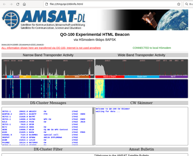
I have written a README file with some instructions about how to run the decoder and the WebSocket server. Once everything is running correctly, we should see a clean 8APSK constellation in the GUI of the decoder, and the HTML page updating with real-time data.
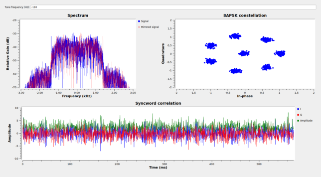
GNU Radio flowgraph GUI
HTML page showing real-time data

The only feature that isn’t implemented yet is displaying the AMSAT bulletins in the lower right part of the HTML page. These seem to be handled here and involve a WebSocket message that has the value 16 in its first byte (or actually in the fourth, if we count the three extra bytes), but I haven’t looked at the details.

Besides this, there could be some corner cases (such as starting the reception of a file mid-way or with severe packet loss) that might make the file receiver thread die. I’ll try to be more careful about these and fix them. Any reports of people using the decoder (whether it works well or not) are welcome.


An erasure FEC for SSDV

$
0
0

SSDV is an amateur radio protocol that is used to transmit images in packets, in a way that is tolerant to packet loss. It is based on JPEG, but unlike a regular JPEG file, where losing even a small part of the file has catastrophic results, in SSDV different blocks of the image are compressed independently. This means that packet loss affects only the corresponding blocks, and the image can still be decoded and displayed, albeit with some missing blocks.

SSDV was originally designed for transmission from high-altitude balloons (see this reference for more information), but it has also been used for some satellite missions, including Longjiang-2, a Chinese lunar orbiting satellite.

Even though SSDV is tolerant to packet loss, to obtain the full image it is necessary to receive all the packets that form the image. If some packets are lost, then it is necessary to retransmit them. Here I present an erasure FEC scheme that is backwards-compatible with SSDV, in the sense that the first packets transmitted by this scheme are identical to the usual \(k\) packets of standard SSDV, and augments the transmission with FEC packets in such a way that the complete image can be recovered from any set of \(k\) packets (so there is no encoding overhead). The FEC packets work as a fountain code, since it is possible to generate up to \(2^{16}\) packets, which is a limit unlikely to be reached in practice.

Motivation and intended applications

The main motivation for this FEC scheme comes from the Longjiang-2 mission. This satellite, also known as DSLWP-B, carried a small camera and transmitted the images from the camera on demand by telecommand using SSDV. The downlink bitrate was usually 125 bps, so transmitting a single image would take around 20 or 30 minutes. It was not uncommon to miss a few of the SSDV packets. Even if the SNR was quite good when the 25 meter radiotelescope at Dwingeloo was used to receive the downlink, there could be occasional problems such as frequency jumps in the on-board TCXO.

In some cases, the missing pieces of the image corresponded to empty parts of the sky that were known to be completely black. In other cases, the missing parts were interesting, so we attempted to receive the complete image by commanding the spacecraft to transmit the missing packets again, before new images were taken that would overwrite the image in the on-board memory. There were two possible ways of doing this. It was possible to send a telecommand that would start the SSDV transmission again, starting from a particular packet number. Alternatively, it was possible to send a telecommand that would cause the transmission of a single SSDV packet.

While the first option seems too wasteful if we were only missing a few packets, in practice it turned out to be the most useful. Telecommand transmission was slow and somewhat unreliable, which meant that it was usually faster to send a single command to restart the image transmission by the point where the first packet was missing than to telecommand the transmission of a dozen packets individually. In any case, keeping track of what packets we were missing for each image was a time consuming and error-prone process.

The FEC scheme proposed in this post is ideal for this kind of situation. Assuming that the SSDV image size is \(k\) packets, the FEC algorithm is able to recover the complete image from any set of \(k\) received packets. This means that if we are missing \(d\) packets from an image, then we can telecommand the spacecraft to transmit \(d\) new FEC packets (or slightly more than \(d\), just in case we lose some of these packets also). We do not need to specify the indices of the packets that we are missing, which is what prevented us from being able to command the transmission of the packets we were missing with a single telecommand (the telecommand would need to carry the list of missing indices, and would be too large).

Additionally, when the image is transmitted for the first time, it is possible to transmit \(k + l\) packets, instead of the usual \(k\). When this is done, we can miss up to \(l\) packets and still be able to decode the image without the need to telecommand a retransmission. The number \(l\) can be fine-tuned during the mission, as we gain knowledge on the reliability that the packet transmissions have and get an estimate of the typical packet loss rate. This approach can also be used in applications where it is not possible to telecommand a retransmission, such as in most high-altitude balloon payloads.

FEC algorithm

The FEC algorithm is a systematic Reed-Solomon-like \((2^{16}, k)\) code over the field \(GF(2^{16})\), used as an erasure FEC. This can be used as a fountain code, because the original \(k\) blocks of data can be encoded as a set of \(2^{16}\) blocks with the property that the the original data can be recovered from any set of \(k\) encoded blocks. It is not necessary to generate or transmit the total set of \(2^{16}\) encoded blocks. The value \(2^{16}\) just gives a limit to the total number of distinct blocks that can be generated. In applications in which this limit is not reached, the pool from which new distinct blocks can be drawn looks endless, as in a true fountain code.

The code works as follows. We assume that we have chosen a numbering \(\alpha_0, \alpha_1,\ldots, \alpha_{2^{16}-1}\) of the elements of \(GF(2^{16})\). Given a message \((a_0, \ldots, a_{k-1})\in GF(2^{16})^k\), first we find the polynomial \(p \in GF(2^{16})[x]\) of degree at most \(k – 1\) such that \(p(\alpha_j) = a_j\) for \(j = 0,\ldots, k-1\). The coefficients of this polynomial can be found by solving a linear system (which has a Vandermonde matrix) or by using Lagrange polynomials. The encoded message is \((b_0,b_1,\ldots, b_{2^{16}-1}) \in GF(2^{16})^{2^{16}}\), where \(b_j = p(\alpha_j)\) for \(j = 0, \ldots, 2^{16}-1\). Note that \(b_j = a_j\) for \(j = 0, \ldots, k-1\) by construction, so the code is systematic.

Given a subset of \(k\) encoded symbols \(\{b_{n_1}, b_{n_2}, \ldots, b_{n_k}\}\), where the indices \(n_j\) are all distinct, we can find \(p\) as the unique polynomial of degree at most \(k – 1\) that satisfies \(p(\alpha_{n_j}) = b_{n_j}\) for \(j = 1, \ldots, k\). Again, the coefficients of \(p\) can be found by solving a linear system with a Vandermonde matrix or using Lagrange polynomials. Once we have found the polynomial \(p\), the original message can be recovered as \(a_j = p(\alpha_j)\) for \(j = 0, \ldots, k-1\).

Note that this algorithm assumes that the receiver, besides having \(k\) encoded symbols, knows the number \(k\) and also knows the indices corresponding to each of the \(k\) encoded symbols.

SSDV packet format

The format of SSDV packets is documented here. This FEC scheme maintains the format of the first \(k\) packets (the ones which correspond to the systematic part of the FEC code) unchanged, so that the typical SSDV decoder software can be used to display the image updating in real time as it is being received. These \(k\) packets are called systematic packets. The scheme is able to generate up to \(2^{16}-k\) distinct FEC packets, which are transmitted after the \(k\) systematic packets. When the receiver has collected a total of \(k\) packets, the complete image can be recovered.

Note that if the receiver is missing some packets at the end of the transmission of the systematic packets, the displayed image doesn’t change until we have collected \(k\) packets. Then it suddenly changes to show the complete image. I don’t know if it would be possible to devise a FEC scheme that allows updating the partial progress while FEC packets are being received. The usual erasure FEC algorithms either recover all the erasures or none of them. I don’t know if there are FEC algorithms that are able to recover a few erasures when they are still missing some data to recover all of them.

To define the packet format for this FEC scheme, I have focused on the variant of SSDV used by Longjiang-2. This differs from standard SSDV in that the sync byte, packet type, and callsign fields, as well as the Reed-Solomon FEC data, are not transmitted, in order to save bandwidth. However, the packet type and callsign fields are still taken into account for the calculation of the CRC-32. Since these fields have fixed values, this is equivalent to not taking them into account and performing the CRC with an initial register value of 0x4EE4FDE1, instead of the usual 0xFFFFFFFF (this value is the “partial CRC” of these implicit fields). The FEC scheme described here can also be applied to the standard SSDV packet format.

The fields from the systematic packets that are protected by the erasure FEC algorithm are the MCU offset, MCU index and payload data fields. This is a total of 208 bytes, which luckily is divisible by 2, so the data to be protected can be encoded as 104 symbols from \(GF(2^{16})\). The FEC algorithm is applied to 104 independent messages of \(k\) symbols, where \(k\) is number of systematic packets (which depends on the size of the SSDV image). Each message to be FEC encoded is formed by taking the pair of bytes in the same position in each of the \(k\) systematic SSDV packets.

The FEC packets have the following fields:

  • Image ID (1 byte). This is the same as in the systematic SSDV packets.
  • Packet ID (2 bytes). This corresponds to the encoded symbol index, so it keeps counting \(k\), \(k+1\), etc., as new FEC packets are generated.
  • Number of systematic packets (2 bytes). This field replaces the image width and image height fields, which are present in all the systematic packets (the FEC scheme assumes that the decoder will receive at least one systematic packet to get this information). Since we need a reliable way to retrieve the number \(k\), this is stored in all the FEC packets. The decoder can find the number \(k\) either by receiving the last systematic packet (which has the EOI flag enabled) or by receiving any FEC packet.
  • Flags (1 byte). The flags are as in the systematic packets, with the addition of flag 0x40 (a reserved bit in standard SSDV), which marks this as a FEC packet.
  • FEC data (208 bytes). This stores the 104 \(GF(2^{16})\) symbols from the 104 independent codewords.
  • CRC-32 (4 bytes). The same algorithm as in the systematic packets is used. The CRC-32 calculation covers all the previous fields (expect the sync byte, if sync bytes are used, which is the case in standard SSDV).

Prototype implementation

I have made a prototype implementation of this FEC scheme in this Jupyter notebook to show the algorithm in action. I used the galois Python package for the arithmetic in \(GF(2^{16})\). The notebook uses the SSDV data from one of the images of the 2 July 2019 solar eclipse taken with Longjiang-2. This particular image consists of 65 packets (so \(k = 65\)).

There are several scenarios demonstrated in the notebook. A rather extreme one involves generating \(2k\) packets (so we have 65 systematic packets and 65 FEC packets) and dropping 50% of them randomly. The results when we process such image with the standard SSDV decoder (which only use systematic packets) are pretty bad, even though most parts of the image are completely black.

SSDV image with only 29/65 systematic SSDV packets received (standard SSDV decoder).

When we process the systematic and FEC packets with the erasure FEC decoder, we are able to recover the complete image.

Complete SSDV image recovered from a set of 29 systematic packets and 36 FEC packets.

Implementation choices

There are some implementation choices that should be specified so that all the implementations of this FEC scheme are compatible. These choices are the following:

  1. A mapping between 16-bit strings and elements of \(GF(2^{16})\). This is used to convert between pairs of bytes and symbols in \(GF(2^{16})\) to apply the FEC algorithm. In doing so, the 16-bit string is formed from the bytes B0 B1 by first taking the 8 bits from B0 in MSB order and then the 8 bits from B1 in MSB order.
  2. An enumeration of all the elements of \(GF(2^{16})\), as \(\alpha_0, \alpha_1, \ldots, \alpha_{2^{16}-1}\). This is used in the FEC algorithm itself.

A straightforward way to define these two choices is to construct \(GF(2^{16})\) as the quotient \(GF(2)[x]/(p)\), where \(p\) is an irreducible polynomial of degree 16 in \(GF(2)[x]\), and to map the bit string \(b_{15}b_{14}\cdots b_1b_0\) to the polynomial\[b_{15}x^{15} + b_{14}x^{14} + \cdots + b_1 x + b_0.\]This fixes the mapping required in 1. Once such a mapping is fixed, 2. can be defined by mapping the indices \(j = 0, \ldots, 2^{16}-1\) to their binary representation in MSB order and then using the mapping in 1. to obtain the corresponding elements in \(GF(2^{16})\).

The galois Python package uses the Conway polynomial\[p(x) = x^{16} + x^5 + x^3 + x^2 + 1\]to construct the field \(GF(2^{16})\), and the rest of the prototype implementation follows the conventions described above regarding how 1. and 2. are defined. For a production implementation, I should think whether it makes sense to maintain the Conway polynomial or whether it can be advantageous for the performance of the computations to choose a different irreducible polynomial.

Future work

I am planning to write at some point a Rust implementation of the FEC algorithm described here. Probably this will have a custom implementation of the arithmetic in \(GF(2^{16})\). The implementation will have an API/ABI as a C library so that it can be called from the usual SSDV software.

ssdv-fec: an erasure FEC for SSDV implemented in Rust

$
0
0

Back in May I proposed an erasure FEC scheme for SSDV. The SSDV protocol is used in amateur radio to transmit JPEG files split in packets, in such a way that losing some packets only cases the loss of pieces of the image, instead of a completely corrupted file. My erasure FEC augments the usual SSDV packets with additional FEC packets. Any set of \(k\) received packets is sufficient to recover the full image, where \(k\) is the number of packets in the original image. An almost limitless amount of distinct FEC packets can be generated on the fly as required.

I have now written a Rust implementation of this erasure FEC scheme, which I have called ssdv-fec. This implementation has small microcontrollers in mind. It is no_std (it doesn’t use the Rust standard library nor libc), does not perform any dynamic memory allocations, and works in-place as much as possible to reduce the memory footprint. As an example use case of this implementation, it is bundled as a static library with a C-like API for ARM Cortex-M4 microcontrollers. This might be used in the AMSAT-DL ERMINAZ PocketQube mission, and it is suitable for other small satellites. There is also a simple CLI application to perform encoding and decoding on a PC.

I have updated the Jupyter notebook that I made in the original post. The notebook had a demo of the FEC scheme written in Python. Now I have added encoding and decoding using the CLI application to this notebook. Using the ssdv-fec CLI application is quite simple (see the README), so it can be used in combination with the ssdv CLI application for encoding and decoding from and to a JPEG file. Note that the Python prototype and this new Rust implementation are not interoperable, for reasons described below.

For details about how the FEC scheme works you can refer to the original post. It is basically a Reed-Solomon code over \(GF(2^{16})\) used as an erasure FEC. To make the implementation suitable for microcontrollers, I have made some decisions about which algorithms to use for the mathematical calculations. I will describe these here.

The finite field \(GF(2^{16})\) is realized as an extension of degree two over \(GF(2^8)\). The field \(GF(2^8)\) is implemented as usual, with lookup tables for the exponential and logarithm functions. In this way, elements of \(GF(2^{16})\) are formed by pairs of elements of \(GF(2^8)\), and the multiplication and division can be written using relatively simple formulas with operations on \(GF(2^8)\).

More in detail, \(GF(2^8)\) is realized as the quotient\[GF(2)[x]/(x^8 + x^4 + x^3 + x^2 + 1).\]This choice of a primitive polynomial of degree 8 over \(GF(2)\) is very common. The element \(x\) is primitive, so the exponential function \(j \mapsto x^j\) and the logarithm \(x^j \mapsto j\) can be tabulated. These two tables occupy 256 bytes each. Multiplication is performed by using these tables to calculate multiplication as addition of exponents. The case where \(x = 0\) is treated separately, since the logarithm of zero is not defined. An element of \(GF(2^8)\) are encoded in a byte by writing it as a polynomial of degree at most 7 in \(x\) and storing the leading term of this polynomial in the MSB and the independent term in the LSB. This is all pretty standard, and it is for example how Phil Karn’s implementation of the CCSDS Reed-Solomon (255, 223) code works.

The field \(GF(2^{16})\) is realized as the quotient\[GF(2^8)[y]/(y^2 + x^3y + 1).\]Here \(x\) still denotes the same primitive element of \(GF(2^8)\) as above. I have selected the polynomial \(y^2 + x^3y + 1\) because \(k = 3\) is the smallest \(k \geq 0\) for which the polynomial \(y^2 + x^ky + 1\) is irreducible over \(GF(2^8)\). The fact that only one term of this polynomial is different from one simplifies the multiplication and division formulas. Each element of \(GF(2^{16})\) is a degree one polynomial \(ay + b\), where \(a, b \in GF(2^8)\). Each of the elements \(a\) and \(b\) is stored in its own byte. Addition of elements of \(GF(2^{16})\) is performed by adding the coefficients of their corresponding degree one polynomials. Since this addition is addition on \(GF(2^8)\), it amounts to the XOR of two bytes, which is very fast.

To compute the formula for multiplication, note that\[(ay + b)(cy + d) = acy^2 + (ad + bc)y + bd \equiv (ad+bc+x^3ac) y + bd + ac\]modulo \(y^2 + x^3y + 1\). Therefore, multiplication only needs 5 products in \(GF(2^8)\) and some additions. In my implementation, for simplicity this is written exactly as such. The field \(GF(2^8)\) is implemented as a Rust type for which a multiplication is defined. This has the disadvantage that each multiplication is performing a logarithm evaluation and some of these are repeated. A more optimized implementation calculates the logarithms of \(a, b, c, d\) only once, but it needs to handle separately the cases when some of these are zero. Perhaps the Rust compiler is smart enough to remove the repeated logarithm evaluations when the straightforward formula is used, and to figure out that the logarithm of \(x^3\) is simply 3. I haven’t checked how much of this it is able to optimize out.

Division is slightly more tricky to calculate. The formula follows from solving\[(cy + d)(ey + f) \equiv ay + b \mod y^2 + x^3 y + 1 \]for the unknowns \(e, f \in GF(2^8)\). Expanding the product as above, this gives a 2×2 linear system, which can be solved with Cramer’s rule. This gives\[\begin{split}e &= \frac{ad + bc}{\Delta},\\ f &= \frac{b(d + x^3c) + ac}{\Delta},\end{split}\]where\[\Delta = c^2 + x^3cd + d^2.\]Note that the irreducibility of \(y^2+x^3y+1\) over \(GF(2^8)\) implies that \(\Delta \neq 0\) unless \(c = d = 0\). This division formula requires the evaluation of 10 multiplications/divisions over \(GF(2^8)\), and some additions.

This implementation of \(GF(2^{16})\) is good for memory constrained systems, because it only requires 512 bytes of tables, but it is still reasonably fast. An implementation that uses tables of exponentials and logarithms in \(GF(2^{16})\) is faster, but it requires 128 KiB of memory for each of the two tables. Even using Zech logarithms, which only requires one 128 KiB table, is prohibitive in systems with low memory. In fact, the implementation of \(GF(2^{16})\) as an extension of degree two over \(GF(2^8)\) can also be interesting for large computers with a lot of memory, because the L1 cache on many CPUs has only 32 KiB, so the cache misses caused by using 128 KiB tables can make the implementation using exponentials and logarithms in \(GF(2^{16})\) slower than the implementation described here.

This implementation of the arithmetic in \(GF(2^{16})\) deviates from the one I proposed in my original post, which was the usual quotient construction as \(GF(2)[z]/(p(z))\) for \(p(z)\) an irreducible polynomial of degree degree 16 over \(GF(2)\). Since the construction of \(GF(2^{16})\) as a degree two extension is better for memory constrained systems, I have chosen it for the “production quality” Rust code, but since there is not a fast and simple way to convert between the two representations of field elements, this means that the Rust implementation and my earlier Python prototype using the galois library are not interoperable. My recommendation is that other implementations of this FEC scheme follow the construction used in the Rust implementation, so that they can be interoperable.

The implementations of the fields \(GF(2^8)\) and \(GF(2^{16})\) as described here are exposed in the public API of ssdv-fec, so these can also be used in other Rust applications and libraries.

Another clever idea in the Rust implementation is how the linear system for polynomial interpolation is solved. This needs to be done both for encoding and decoding. The problem can be stated generically as, given a polynomial \(p \in GF(2^{16})[z]\) of degree at most \(m\) and its values at \(m + 1\) distinct points \(z_0, \ldots, z_m \in GF(2^{16})\), compute the values \(p(z)\) at other points \(z \in GF(2^{16})\). The way I presented this in the original post was conceptually simple. The linear system for solving the coefficients of \(p\) in terms of \(p(z_0), \ldots, p(z_m)\) has a single solution, and in fact the matrix of this system is an invertible Vandermonde matrix. Therefore, we can compute the coefficients of \(p\) and then evaluate it at the required points \(z\).

A naïve implementation of this idea solves the system by Gauss reduction. This has the disadvantage that the Vandermonde matrix needs to be stored somewhere in order to perform the row operations that convert it to the identity matrix. If we want the implementation to have a minimal memory footprint, we would rather not store this matrix, which only plays an auxiliary role.

Luckily there is an alternative way to approach this problem that does not require storing a matrix. The polynomial \(p\) is the Lagrange polynomial, and there are some explicit formulas for it. If \(z\) is not equal to any of \(z_0,\ldots,z_m\), we have\[p(z) = l(z) \sum_{j=0}^m \frac{w_j p(z_j)}{z – z_j},\]where\[l(z) = \prod_{j=0}^m (z – z_j),\]and\[w_j = \prod_{0 \leq k \leq m,\ k \neq j} (z_j-z_k)^{-1}.\] This formula gives a way of calculating \(p(z)\) without using any other memory besides that used to store the terms \(p(z_0),\ldots,p(z_m)\) and their corresponding points \(z_0,\ldots,z_m\).

Since during encoding or decoding the formula above is to be evaluated for many different values of \(z\), the input data \(p(z_0),\ldots,p(z_m)\) is modified in-place, substituting each \(p(z_j)\) by \(w_j p(z_j)\), calculating the product \(w_j\) to do this. This makes the evaluation of \(p(z)\) using the formula faster.

Testing gr4-packet-modem through a GEO transponder

$
0
0

During the last few months, I have been working on gr4-packet-modem. This is a packet-based QPSK modem that I’m writing from scratch using the GNU Radio 4.0 runtime. The gr4-packet-modem project is funded by GNU Radio with an ARDC grant, and its goal is to produce a complete digital communications application in GNU Radio 4.0 that can serve to test how well the new runtime works in this context and also as a set of examples for people getting into GNU Radio 4.0 development. I have presented gr4-packet-modem in the EU GNU Radio days (see the recording in YouTube).

In July, Frank Zeppenfeldt, who works in the satellite communications group in ESA, got in touch with me regarding an opportunity to test gr4-packet-modem on a C-band transponder on Intelsat 37e. His group is running a project with industry about a test campaign of IoT communications over GEO satellites, and they have rented a 1 MHz C-band transponder on Intelsat 37e for some time. The uplink is somewhere around 5.9 GHz, and the downlink somewhere around 3.7 GHz. As part of the project, they have setup a PC and a USRP B200mini in a teleport in Germany that has a large antenna to receive the downlink. There is remote access to this PC, so all the downlink part of the experiments is taken care of: IQ recordings can be made and receiver software can be run in this PC. Therefore, if I could set up an uplink station at home in Madrid (which is actually slightly outside the edge of the Europe C-band beam, as it can be seen in this document), then I would be able to run some tests of gr4-packet-modem by running the transmitter in my laptop and the receiver in the remote PC at the teleport.

As I mentioned to Frank when he proposed this experiment, I haven’t implemented an FEC for the payload of the packets in gr4-packet-modem, because I wanted to have full freedom in setting the size of each packet (to test latency with different packet sizes), and a good FEC scheme usually constraints the possible packet sizes (see gr-packet-modem waveform design for more details). Testing a modem that uses uncoded QPSK over a GEO channel is somewhat pointless, but Frank and I agreed that this would be a fun experiment, even if not too interesting from the technical point of view. In the rest of the post I explain the test set up and results.

For the uplink station I used a 24 dBi flat-panel antenna that I had around for some WiFi experiments. The antenna is designed for 5 GHz WiFi, but according to the datasheet the C-band uplink frequency used by the transponder is covered, since it is close enough to some WiFi channels at 5.8 GHz. The uplink is circularly polarized, and this antenna has linear polarization, so there is a 3 dB polarization mismatch loss.

I needed a power amplifier to get a reasonable amount of power, so I purchased an SBB5089 + SE5004 amplifier from Aliexpress. These are 5.8 GHz 2W amplifiers that are sold for about 15€. For this price, they might not be great, and they might not really give 2W (perhaps they give 1W, which is okay). Frank is using some of these in his experiments, so I decided to get one too because it’s a great price for a one-off experiment.

The rest of the uplink station is a B205mini, a lab power supply to power the amplifier, and a laptop. The power amplifier is said to have 40 dB of gain, and I can attest that the B205mini has enough drive to saturate it. The power amplifier is powered by 5V USB, but using a lab power supply is handy because it lets me see how much current the amplifier is taking. As the amplifier gets warmer (and it does get really hot indeed), it is quite apparent how the current consumed on transmit drops. Since this most likely means that the gain is dropping with the increase in temperature, and so the output power is dropping too, I increased the USRP gain a little to compensate when this happens. I tried to keep roughly the same current on transmit while running the experiment (speaking from memory, around 900 mA at 5V).

Before running any experiments on the satellite, I did some tests of the power amplifier to get a feeling for how much TX gain I would need in the USRP. I did a two-tone test (with 10 kHz tone separation) and looked at the output of the power amplifier with the same USRP, while monitoring the current consumption of the amplifier. I set an operating point based on third-order intermodulation products. Basically, I increased the gain as far as possible while still having reasonable intermodulation products (20 dB down or so). The TX gain for this was around 73 dB. The maximum TX gain of the B205mini is 89.8 dB, so it can give much more drive than what is needed for this amplifier.

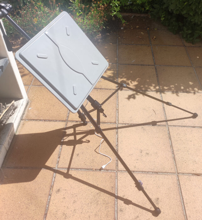
I placed the flat-panel antenna on a camera tripod. Intelsat 37e is at 40.8 deg elevation at my location, so the tripod is placed in a very awkward way when pointing to the satellite. I first set up the antenna pointing by transmitting my two-tone test and looking at the downlink on the remote PC. The next day I waited until the sun was at the same azimuth as Intelsat 37e and checked the shadows, and my azimuth pointing seemed spot on.

5.8 GHz antenna pointing to Intelsat 37e

For the test of gr4-packet-modem, I decided to use a baudrate of 125 symbols/second based on how much SNR I was getting with the two-tone test. This ended up giving me an Es/N0 of around 9.5 dB, meaning that short uncoded QPSK packets could often be decoded without errors. The link budget is thus that a 22 dBW uplink (polarization losses and the fact that the amplifier probably does less than 2W have already been taken into account) gives around 30.5 dB·Hz CN0 in the downlink. This is on the ballpark of the link budget that Frank gave me for the experiments he had run from ESTEC (Netherlands).

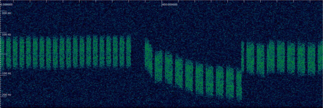
During the test, I found that the frequency instability was much higher than what the default configuration of gr4-packet-modem is prepared to deal with. The signal drifted by hundreds of Hz over the course of a few minutes, so I frequently need retune the receiver manually by looking at the spectrum of the received signal in GNU Radio 3.10. I also needed to increase a lot the frequency search range of the Syncword Detection block and the bandwidth of the Costas Loop in the gr4-packet-modem receiver. So I guess the experiment was not so technically uninteresting in the end, as it provided the chance to test the receiver in very different operating conditions regarding frequency drift compared to all the other tests I have done with this software. The figure below shows a waterfall of the IQ signal recorded at the receiver. The frequency drift is quite clear. There is also a manual retuning visible.

Waterfall of an IQ recording of the gr4-packet-modem test on Intelsat 37e

In the remote PC on the teleport I ran a GNU Radio 3.10 flowgraph that decimated the signal to 500 sps (4 samples/symbol, which is what the modem usually runs at), recorded this to an IQ file and also wrote it to a FIFO. The gr4-packet-modem packet_receiver_file application was used to read from the FIFO and decode the data in real time (although latency was quite large at such a low sample rate). The plot_symbols.py script showed constellation plots of each received packet. gr4-packet-modem is normally used with TUN devices on Linux to implement IP communications. In this case I sent ping packets from my laptop in Madrid and received them in the teleport PC. There was no path for the ping replies to be sent back. This was a one-way test only.

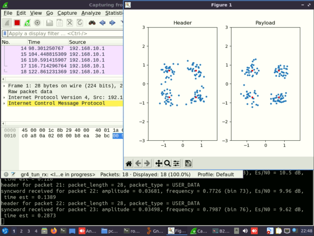
The figure below shows a screenshot of the remote PC during the test. We can see the constellation plot for one packet (which gives evidence that at this SNR there is a reasonable probability of decoding short packets without errors), a Wireshark screen showing the received pings (a ping packet is sent every 6 seconds, since it takes around 4 seconds to transmit at 250 bps), and a terminal with the log of the gr4-packet-modem receiver, which contains Es/N0 estimates.

gr4-packet-modem receiver during the Intelsat 37e test

First I tested transmitting ping packets as short as possible (ping -s 0, which gives 28-byte IPv4 packets). Most of these packets were decoded successfully. Then I tested the normal ping size (which gives 84-byte IPv4 packets). For these the error rate was somewhat higher. The moment when the ping size is changed can be seen in the waterfall shown above.

I have published the IQ recording for this test as the dataset “Test of gr4-packet-modem through an Intelsat 37e C-band transponder” in Zenodo. This recording is already in cf32_le format at 4 samples/symbol, so it can be processed directly by the packet_receiver_file application. However, to get valid decodes it is necessary to increase the frequency search range (which can be done with command line arguments) and the Costas Loop bandwidth (which currently can only be done by editing the values declared in payload_metadata_insert.hpp).

Viewing all 64 articles
Browse latest View live